



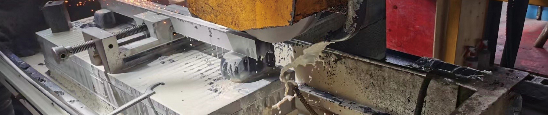

The right slitter knife bevel angle helps a rotary cutting edge separate the material cleanly without unnecessary distortion, dust, burrs, or premature chipping. But the right angle for thin tissue is not necessarily right for coated board, a laminated packaging film, an adhesive tape, or stainless-steel coil. Even two knives described as “45-degree blades” may have different cutting profiles if one drawing measures an included edge angle while the other records a grind angle from a blade face.
This technical and purchasing guide explains how to interpret a slitter blade angle, compare single-bevel and double-bevel designs, and select a practical starting geometry for different substrates. It is written for paper and film converters, metal-coil processors, maintenance engineers, slitter-rewinder OEMs, and buyers ordering made-to-drawing replacement knives. The aim is to help you produce a defensible drawing and a controlled qualification plan—not to pretend that a universal angle chart can replace actual cutting trials.
Quick answer: First identify whether the machine uses rotary shear, razor, score/crush, or metal-coil rotary shear cutting. Confirm whether the supplier's “angle” means the included cutting-edge angle, the angle of one ground face, a secondary relief angle, or the knifeholder's cant angle. For sensitive webs, evaluate a geometry that reduces material contact after fracture while still retaining enough tip strength. For stronger, thicker, or shock-loaded duty, investigate stronger edge support and a suitable blade body. Then validate the candidate against the real product, machine setup, and defect limits.
GUANG CHUAN supplies application-specific industrial machine knives for paper, film, metal foil, and coil-related production. Buyers who first need an overview of blade construction and machine compatibility can read our circular slitter knives selection guide. This article goes deeper into one particularly important purchasing detail: cutting-edge geometry.
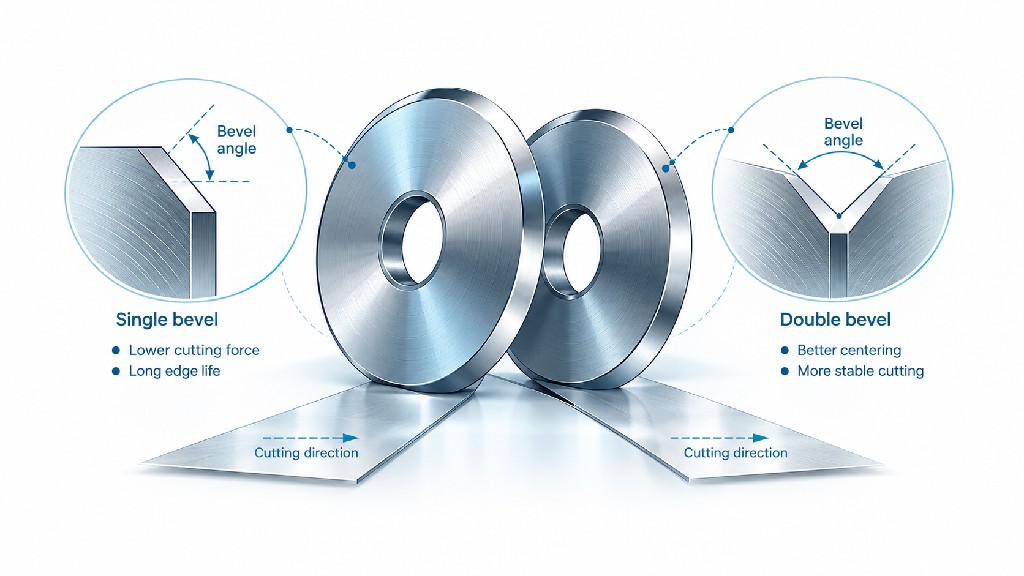
A rotating knife works at a narrow local region called the cut point. In a shear-slitting arrangement, the upper knife and lower knife cooperate to produce a scissors-like separation. The knife edge must concentrate force at the cut point, but its flanks also have to pass the freshly separated material. An edge that is geometrically thin can reduce the initial disturbance of delicate webs. An edge that is too thin for the material, side-load, or holder rigidity may chip, roll, bend, or fail before a planned production campaign ends.
A more supported edge usually survives mechanical loading better, yet it may push more material sideways as the web travels past the bevel. That extra displacement can produce paper dust, edge ridges, film stretching, foil curl, or a wider damaged zone. A practical bevel is therefore a compromise among penetration, edge support, material displacement, friction, and manufacturing repeatability.
Industry specialists describe this trade-off in similar terms. The Converting Quarterly discussion of knife shape explains how primary and secondary bevels affect web deformation after fracture. The Valley Grinding Principles of Shear Slitting manual provides illustrated profile comparisons and explicitly relates edge support to web distortion. Neither source claims that a single cutting angle is best for every product.
What matters commercially is not the appearance of a new knife under a microscope alone. A blade must deliver the specified slit width, an acceptable edge profile, predictable life, stable running, and a manageable regrinding cost. This is why an apparently minor change to the rotary knife bevel can influence scrap, changeover frequency, customer complaints, and the total cost of a cutting program.
The included edge angle is the angle contained between the two surfaces that meet at the cutting edge. On a simple symmetrical double-bevel knife, each straight flank may be inclined by the same amount relative to the central blade plane. If each flank is measured at 20 degrees from that plane, the included edge angle is 40 degrees. A single-bevel blade has one flat face and one sloped face, but the angular reference used on a drawing still needs to be stated. It is unsafe to assume that a supplier's catalog number represents the same geometric measurement as your existing drawing.
For clarity, write “included edge angle: 40°” when that is the intended acceptance dimension. If the drawing instead specifies the grinding angle of one face, identify the reference face, whether the angle is measured from the face or a plane perpendicular to it, and the face on which the grind must appear. This avoids a surprisingly common procurement error: receiving a knife that is dimensionally correct in diameter and bore but incorrectly sharpened at the circumference.
The primary bevel is the short ground region immediately adjacent to the cutting tip. A secondary bevel is formed behind it and can reduce the amount of knife material interacting with the freshly cut web. A compound bevel combines those stages. A back bevel is a grind on the opposite side of the blade; its function depends on whether the knife is used for shear slitting, razor cutting, or log-roll slitting. Valley Grinding uses these definitions in the terminology section of its published manual. Their existence is a reason to ask for a cross-section rather than a one-line “bevel: 45°” entry.
Another term, hollow-ground bevel, describes a concave ground profile rather than a straight flat face. A hollow ground area can lower the contact area between the web and the blade, but it also changes local support, resharpening methods, and the way a measuring fixture should inspect the edge. Two knives may share the same measured local tip angle and still behave differently because their relief profiles differ.
The cant angle, sometimes called shear angle, is an installation or holder orientation parameter. It describes the angular relationship of the top knife to the bottom knife in the machine. It is distinct from the bevel ground into the edge. The DIENES Slitting Reference Guide treats knife bevel geometry, holder shear angle, overlap, and side load as separate subjects. A buyer who orders a “0.5° bevel” after reading a cant-angle setting may receive a completely inappropriate knife.
Important drawing rule: The terms bevel angle, edge angle, cutting angle, cant angle, and shear angle are not interchangeable. Every quotation should include a cross-sectional profile, orientation of the working shear face, and an explicit angle reference.
| Term on drawing | What it controls | Typical question to ask | Must not be confused with |
|---|---|---|---|
| Included cutting-edge angle | Local wedge geometry where the two faces meet | What angle is measured between the two edge surfaces? | One-face grinding angle |
| Single-face bevel angle | Slope of a ground face relative to a specified datum | Which face and reference plane are used? | Included angle of a symmetric double bevel |
| Primary bevel width | Size of the land near the cutting tip | Is width measured on the face or in radial projection? | Blade body thickness |
| Secondary or relief angle | Material clearance behind the primary land | Is the relief flat, stepped, or hollow ground? | Primary edge angle |
| Knifeholder cant angle | Top-to-bottom knife orientation at the machine cut point | What is the holder OEM's installed setting? | Any ground blade bevel |
| Overlap or penetration | Engagement between cutting elements | Where are zero and the measurement direction defined? | Bevel angle |
A single bevel slitter knife has a working edge ground predominantly from one side, leaving the other side comparatively flat or relieved according to the design. This geometry can be useful where the cut must be referenced to a flat shear face and where the blade needs substantial support. The orientation is critical: reversing the knife may move the working edge away from the intended contact face or shift the slit position. A “single bevel” purchase description does not identify whether the blade is right-hand, left-hand, upper, or lower.
For harder or thicker converting webs, a correctly supported single-bevel design can be a sensible trial candidate. The DIENES reference guide describes single-bevel upper knives as suitable for tougher materials and lists primary-bevel widths of approximately 0.6–3.0 mm for its illustrated designs. Those figures are published design examples from one supplier, not an angle or width requirement for all blades. They are especially not permission to install an arbitrary primary land on a metal-coil rotary shear.
A double bevel slitter knife has two bevel regions in the profile, but catalogs use the phrase in different ways. Some mean two sloped flanks meeting symmetrically at the edge; others describe a primary and secondary bevel on a working face. The correct answer is always the dimensioned section drawing. In web converting, a compound or double-beveled top knife can reduce the amount of material pushed aside after separation while keeping a stronger local edge than a long, uniformly thin wedge.
The DIENES guide illustrates a double-bevel top knife with a primary bevel width of approximately 0.5 mm and describes it as widely applicable to medium and lighter webs. It also identifies a double hollow-bevel option with a primary land around 0.3–0.5 mm for light paper, plastics, foil, and adhesive materials. These values concern the geometry of those illustrated top-knife designs; they are not recommended included edge angles and are not universal manufacturing tolerances.
A compound design can keep a robust tip while removing material behind it. That is often the more productive question than “Should I buy the sharpest possible blade?” The primary section deals with the immediate fracture; the secondary section manages how the web leaves the cut point. When dust and post-cut scuffing dominate, a relief design may be worth more than a small change in the nominal primary angle.
Hollow grinding deserves special attention on sticky or delicate materials, where reduced contact can help limit buildup and friction. However, the actual result depends on the finish of the hollow section, coating condition, lateral runout, cleaning regime, and the machine's side loading. A badly maintained hollow-ground knife may perform worse than a properly ground flat bevel. A qualified supplier should therefore quote the entire cross-section, not just an attractive grinding label.
| Profile family | Potential advantage | Trade-off to evaluate | Initial application hypothesis |
|---|---|---|---|
| Single bevel / one-sided edge | Defined flat reference face and edge support | Orientation and possible asymmetric material displacement | Tougher webs or design requiring a precise working face |
| Symmetrical two-flank wedge | Balanced geometric penetration | May not suit a shear arrangement requiring a flat mating face | Razor-style or other approved configurations |
| Primary plus secondary bevel | Tip support with relief after separation | More parameters to specify and inspect | Paper, film, foil, and demanding converting lines |
| Double hollow-ground section | Reduced web-to-blade contact potential | Specialized grinding and geometry control | Delicate or adhesive webs after an actual cutting trial |
| Near-square shear edge | High section support | Different load and fracture mechanics from thin-web knives | Purpose-designed metal-coil rotary shear tooling |
To clarify whether your machine requires a top knife, bottom knife, score cutter, or another design, see our explanation of circular slitter blades versus rotary slitter knives and the top and bottom slitter knife product range.
Industrial literature does offer numerical guidance, but the numbers must be kept attached to their context. Valley Grinding's shear-slitting manual illustrates profile angles of 30°, 45°, 60–65°, and 85–90°. It associates a 45° illustrated profile with common paper cutting, while indicating that a 30° profile gives relatively little web displacement but weaker tip support. Its near-90° illustration shows a particularly strong tip with greater web disturbance. The figures demonstrate a design trade-off; they do not establish a worldwide “30° for plastic, 45° for paper, 60° for steel” standard.
The same manual illustrates a compound profile with different local and backing angles. The practical insight is that the bevel's shape behind the first contact can be as important as the nominal tip number. Because the printed angle references in different drawings and supplier catalogs are not necessarily identical, reproduce the manufacturer's cross-section when transferring a published example to a purchase specification.
| Published example | What the source states | Useful engineering interpretation | Important limitation |
|---|---|---|---|
| Valley Grinding: 30° profile | Low web distortion, lower tip strength | Possible starting comparison for a sensitive web where edge survival is adequate | Illustrated profile geometry, not a universal material recipe |
| Valley Grinding: 45° profile | Common paper-cutting example with moderate support | Useful benchmark for a paper-slitting evaluation | Must reproduce the source's angle reference and blade style |
| Valley Grinding: 60–65° profile | More support; compound relief may reduce deformation | Consider the interaction between supported tip and backing relief | Not an automatic recommendation for heavy-duty metal coil |
| Valley Grinding: 85–90° profile | Strong tip but high web distortion | Shows why maximum strength is not always minimum total cost | Not a general-purpose target for thin films |
| DIENES: single-bevel primary width | Approx. 0.6–3.0 mm in its illustrated top-knife family | Check land width together with bevel and body design | Width is not an angular value |
| DIENES: double-bevel primary width | Approx. 0.5 mm in its illustrated design | Short land and backing relief may lower dust | Not a dimension for every diameter or substrate |
| DIENES: double hollow primary width | Approx. 0.3–0.5 mm in its illustrated design | One comparison option for fine or adhesive webs | Actual result depends on holder, finish, and side load |
The underlying references are the Valley Grinding manual, blade profiles section and the DIENES guide, top-knife bevel sections. They provide evidence for evaluating edge profiles, not substitutes for the machine OEM's geometry and operational safety limits.
A short calculation explains why a thicker wedge can change what a web experiences after the first fracture. Consider an ideal straight-sided, symmetric wedge with an included edge angle of θ. At a radial distance L behind the tip, the theoretical wedge thickness is t = 2 × L × tan(θ/2). This formula assumes two straight symmetric flanks, a negligible tip radius, and no compound or hollow relief. It is a two-dimensional geometry illustration, not a predictive cutting-force model.
For a comparison at L = 0.50 mm, the wedge cross-section becomes progressively thicker as the included angle rises. Real shear-slitting tools often use asymmetric surfaces and relief lands, so the calculation should not be blindly applied to a commercial knife. Its purpose is to show why the edge profile can displace more material behind the tip even when both edges are technically sharp.
| Included angle θ | Half-angle θ/2 | Calculated wedge thickness at L = 0.50 mm | What changes geometrically |
|---|---|---|---|
| 30° | 15° | 0.268 mm | Thin local wedge; less cross-sectional support |
| 40° | 20° | 0.364 mm | Moderate geometric increase in section |
| 45° | 22.5° | 0.414 mm | Intermediate illustrated profile |
| 60° | 30° | 0.577 mm | Substantially thicker material behind the tip |
| 65° | 32.5° | 0.637 mm | Even more cross-sectional support |
Calculation check: At θ = 60° and L = 0.50 mm, t = 2 × 0.50 × tan(30°) = 0.577 mm, rounded to three decimals. At 30°, the same expression gives approximately 0.268 mm. No claim is made that the 60° blade generates twice the real-world cutting force or lasts twice as long; the table contains calculated thicknesses only.
In practice, radius at the tip, side-face polishing, coatings, fracture mechanics, web tension, counter-knife design, and the grinding land all influence force and finished-edge quality. Ask the supplier for the profile shape and measurement method if a numerical bevel specification is intended to be comparable between quotations.
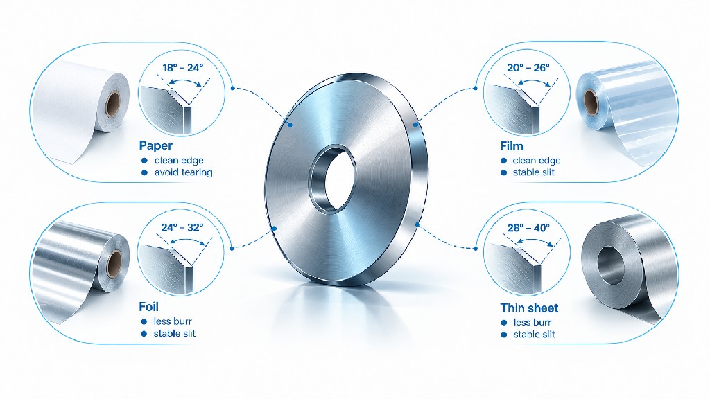
Use the following matrix as an engineering screening tool. It intentionally does not prescribe one degree value for each raw material, because substrate names do not describe the full cutting duty. A 12-micrometer PET film, a 150-micrometer laminated PET structure, and a filled film can differ in thickness, stiffness, abrasion, and failure mode even though all are loosely described as plastic film. A useful selection table identifies which geometry to trial first, what could go wrong, and how success will be measured.
| Material / product | Typical edge-quality problem | Geometry to evaluate first | Validation priority |
|---|---|---|---|
| Light tissue / lightweight paper | Dust, fuzz, tearing, curl | Fine supported edge with compound or hollow relief | Dust, edge fibers, consistent cut point |
| Copy paper / uncoated paper | Fiber pull-out, paper dust | Documented paper-shear profile; compare supported medium edge and relief | Edge cleanliness, knife life |
| Coated paper / labels | Abrasive wear, coating flakes | Supported fine primary bevel plus reduced side contact | Dust, coating damage, wear progression |
| Kraft paper / board | Fuzzy edges, high cutting resistance | More supported primary land, then optimize relief | Complete cut and tip durability |
| PET / BOPP packaging film | Stretch, whitening, uneven slit | Fine, clean edge with controlled relief for the approved cut method | Edge deformation and winding quality |
| PE / soft stretch film | Necking, smearing, wrinkling | Low-drag profile; careful contact and tension control | Stable separation without stretching |
| Metallized film / laminates | Layer cracking, delamination, dust | Compound profile tailored to laminate stack | Layer integrity and particle release |
| Adhesive tape / label stock | Pickup, edge residue, wandering | Polished or hollow-relieved geometry where appropriate | Adhesive accumulation and slit tracking |
| Aluminum foil / copper foil | Wrinkle, curl, particles, burr | Precision shear edge with minimal unnecessary contact | Magnified edge inspection, foil handling |
| Nonwoven / textile | Fuzz, uncut fibers, fiber drag | Match shear, razor, or score mechanism before bevel choice | Complete fiber separation and edge fray |
| Carbon-steel coil | Burr, rollover, blade edge damage | Purpose-designed opposing rotary shear edges, not thin-web tip assumptions | Clearance, edge zones, tolerance |
| Stainless-steel coil | High loads, burrs, chipping | Load-capable shear edge and matching tool steel | Blade integrity, edge burr, sustained setup |
This table groups materials by likely failure mode, not by a fabricated universal bevel-angle range. A qualified drawing starts from the known machine and a representative material sample. If the plant already has a dependable knife for a similar application, request its measured profile as the baseline and make only one controlled change at a time.
With tissue or lightweight paper, the visible cut can look acceptable while microscopic fibers and airborne dust become a production problem. Light webs may not resist lateral displacement strongly, so they can bend around a blunt or poorly relieved cutting edge before separating. A design with a supported fine primary land and a smooth secondary relief deserves investigation because it can keep the cut point localized without forcing the web to follow a thick blade section.
The correct choice still depends on holder stability. At high web speed, a theoretically fine tip that oscillates laterally can make worse dust than a somewhat stronger tip in a stable holder. Ask whether the top knife is driven or rotated by contact with the bottom knife; ask how the bottom anvil is supported; and check whether the machine produces a stable cut on every slit station. DIENES notes that especially sensitive light papers can benefit from motor-driven knives where slip between a friction-driven top knife and the bottom component would otherwise influence cut quality.
For qualification, collect dust from an equal length of product, inspect the cut using the same lighting and magnification, and record any strand-like fibers that project from the edge. Do not accept a geometry solely because it reduces visible dust at the first minute of the run. Observe it again after a representative production interval because early wear or buildup can reverse the result.
Uncoated writing and printing paper is often a good place to establish a reference profile for a converting line. Valley Grinding's illustrated 45° paper profile is a useful documented example, but it must be interpreted using that manual's cross-sectional definition. It does not justify ordering every paper knife at an unspecified 45°. The existing successful knife, the required holder geometry, and the accepted cut profile should define the baseline.
Coated papers add another variable: mineral fillers and coatings may abrade the edge even when the base fibers are easy to separate. A blade with excellent initial sharpness can gradually develop a rounded cutting tip, increasing dust or causing uneven separation. In such a case the buyer should compare edge geometry and knife material together, while keeping them as separate variables in the test. The best explanation of a failed trial is not “the angle was wrong” if one of the specimens also used a different hardness or surface finish.
Labels can add release liners, adhesive, face stock, and printing layers. Cutting behavior varies across a stack: a profile that cleanly cuts the paper face stock may drag adhesive or disturb a silicone-coated liner. Specify whether the task is through-slitting all layers or a more selective cut, because a different knife mechanism may be needed. Check the slit under magnification for liner damage, coating flakes, adhesive transfer, and intermittent failure along the machine direction.
Kraft paper and board are often more resistant to local fracture than thin tissue. A very narrow wedge may lack adequate edge support under the required side load. Start from a mechanically sound primary bevel, then consider how a secondary grind can reduce drag behind the tip. If the edge still feathers, it may be necessary to adjust the cut point, knifeholder or lower knife rather than continuing to sharpen the top knife thinner.
Board stiffness also changes the web path. An unsupported sheet may push away from the cutting point, while thick or multilayer board can require more drive capability than a lightly loaded paper web. The DIENES overview of shear cutting discusses the use of appropriate configurations and driven upper knives for demanding board applications. Review the actual machine duty before requesting a bevel change from the supplier.
Film slitting often fails through stretching or edge damage rather than obvious fibrous dust. PET and BOPP may appear to separate cleanly at one speed but display edge whitening, a distorted layer, or a narrow ridge when inspected later. A sharp and geometrically consistent edge helps limit uncontrolled strain, while an appropriate relief profile reduces the distance for which the material remains in contact with the knife after the slit begins.
Do not decide on a bevel from polymer name alone. Film thickness, orientation, residual stress, coatings, lamination, winding tension, and whether the web is supported at the cut point all matter. An optical film intended for display production may have much stricter particle and edge-wave requirements than an ordinary packaging film of similar thickness. Both may call for a very fine edge, yet they can justify different body stiffness, material grade, and polishing requirements.
For a useful comparison, keep the same bottom knife and holder settings, inspect specimens from both sides of the slit, and compare after a stable winding period. A slight change in the edge shape can shift which side of the web experiences more deformation. Photographs should therefore identify the knife side, machine-direction orientation, and sampling position, rather than simply label one sample “good” and the other “bad.”
Soft polyethylene and stretch films can elongate ahead of the tip instead of developing a clean, immediate fracture. A fine edge with low after-cut friction is generally worth evaluating, but simply decreasing the included angle may not solve the problem. If the holder is unstable, the web tension is too low or inconsistent, or the blade has an oversized edge radius, the film may wrinkle or stretch regardless of its nominal bevel.
Where a film is prone to smearing or adhesive-like pickup, distinguish true blade wear from accumulated material. A polished secondary flank and a cleaning protocol may make a larger difference than changing the tool steel. Avoid specifying a special coating without verifying compatibility with the substrate, because coatings can alter local edge radius or require different regrinding procedures.
A multilayer structure combines materials that fail differently. A PET/adhesive/PE laminate, for example, might contain a relatively stiff outer layer, a softer sealant layer, and one or more bonding interfaces. The slit can show a visually good top layer while the lower layer stretches or separates unevenly. This is one reason a generic “film bevel angle” recommendation has low predictive value.
Request a sample of the complete commercial laminate, including the coatings and nominal thickness range. Define the quality limit in terms of delamination, sealant drag, particle generation, and acceptable edge width, then test one geometry revision at a time. If only the nominal film is supplied, the knife maker cannot reliably judge the real stack. GUANG CHUAN's clearance, overlap, and side-force setup guide explains related machine variables that should remain controlled while comparing blade profiles.
Thin metal foils are sensitive to very small defects. A visible burr or curled edge can interrupt subsequent coating, winding, laminating, or assembly steps. Because foil has limited thickness and can deform under a modest disturbance, a high-quality shear cutting point and consistent machine alignment are often more important than choosing an extreme bevel angle in isolation.
For aluminum foil and copper foil, start by confirming the approved cutting mechanism. Is this a precision top-and-bottom shear system? Is there a supported lower anvil? Does the machine use individually mounted top knives, a shaft-mounted arrangement, or a specialized cutting head? Different mechanisms need different contact geometry. An edge that works for heavy coil shearing should not be copied automatically into a delicate foil rewinder.
When comparing candidate bevels, inspect for fine burrs, side curling, local tearing, coating or oxide debris, and changes in roll winding. Use an inspection technique appropriate to the specified defect size. A hand lens may be enough to identify major damage but not to qualify a particle-sensitive foil application. The knife should also be inspected for chips because a small hard-particle impact can introduce repeated defects at the same circumferential location.
Consider the material grade and surface finish together. A sharp hard edge may reduce gradual abrasive wear, but a brittle material can chip when the system experiences an impact or contact error. For a more thorough metallurgical decision, compare the evidence in our D2 versus M2/M42 HSS versus tungsten carbide slitter knife guide. Choose the geometry and substrate grade as a matched system rather than making an uncontrolled material upgrade.
Adhesive converting often turns blade maintenance into a problem of surface condition as much as cutting geometry. Residue can adhere to the edge or secondary surface, creating a thicker effective profile, generating heat, and causing web tracking problems. A very sharp new blade may initially look ideal, but its performance can change sharply as deposits accumulate.
Hollow relief can reduce the surface available for contact in some designs. DIENES specifically discusses double hollow-ground top knives for adhesive and light web slitting, citing less material contact and a clean cut profile in its guide. That observation supports including hollow relief as a trial candidate. It does not prove that every adhesive formula responds identically, especially when temperature, adhesive chemistry, coat weight, and liner construction vary.
When preparing a drawing, identify the side of the knife that contacts the adhesive-bearing layer and the side that must preserve the finished product's clean edge. Test performance after a defined operating interval rather than making the purchasing decision only on the first clean sample. Record cleaning time, deposit mass or a consistent visual residue score, slit tracking, and whether the edge can be restored without grinding. A geometry that reduces cleaning stops may be financially better even if both candidates have similar mechanical cutting life.
Log-roll slitting must be handled separately. It is not the same operating mechanism as paired rotary shear slitting. In some log-slit applications, the primary bevel and an opposing back bevel help manage forces when cutting wider roll sections. Do not transplant a back-bevel recommendation from a log-slit manual into a shear-slitter drawing without checking the mechanism and resulting loads.
Nonwovens and textiles contain fibers that may stretch, pull out, or remain joined after the cutting point passes. A fine razor can work for a lightly supported film-like textile, but other woven or bulky materials may benefit from an appropriate shear, score, or even a specialized heated cutting process. The bevel decision follows the cutting method, not the other way around.
For a shear-slitted nonwoven, evaluate whether the knife initiates a full separation across the web thickness or merely pushes fibers away. Compare the edge under tension and after relaxation, because fibers can spring back and reveal partially cut strands. Ask whether the upper and lower knives maintain contact at the required location and whether the material is consistently supported by the machine.
Flexible foam and soft composites introduce compression. A very fine wedge may enter easily yet leave a distorted band when the material recovers. Crush or score cutting has different contact and tip-radius requirements from conventional rotary shear slitting. If a supplier recommends a specific “bevel angle for foam,” ask which cutting system and foam density the recommendation assumes. A correct profile for a dense abrasive composite may be unsuited to a soft cellular polymer.
For mixed waste, heavily filled products, or intermittent reinforced layers, toughness and impact resistance become important. A locally strengthened tip may prevent damage, but excessive edge bulk can compromise the product. In these cases, a documented test with the difficult material at its maximum normal thickness is more valuable than a polished catalog photograph.
Metal-coil slitting often uses two opposed circular shear tools mounted on shafts, with spacers and support rings controlling their positions. The strip is locally deformed until a shear and fracture process separates it. Finished metal edges show characteristic zones such as rollover, burnish, fracture, and burr. The main tooling questions concern opposing edge support, clearance, penetration, alignment, strength, and blade metallurgy. The thin-web “very fine bevel” logic cannot be copied into this setup unchanged.
Some metal-shear knife profiles are nearly square at the working edge, while others employ a designed chamfer, relief, or compound section to handle a particular alloy or assembly. In every case, the mating edge, tool dimensions, side clearance, and load have to be considered together. A knife with too much removed behind the cutting edge can lose the support needed to withstand high local stresses. A strong edge with poor machine alignment can still produce burrs and premature wear.
For a practical guide to defects, see GUANG CHUAN's metal-coil slitting burr troubleshooting article. Customers specifying replacement sets can also review our precision rotary slitter knives for metal-coil lines.
DIENES publishes useful contextual data for rotary shear cutting of metal strip: it describes applications around 0.01–16 mm material thickness and tensile strengths around 300–2,400 N/mm², and offers illustrative cutting-gap guidance of roughly 10% of strip thickness for steels depending on strength, versus roughly 5% for softer metals such as copper, brass, and aluminum. These are the supplier's broad process descriptions. They describe cutting clearance rather than a slitter knife bevel angle, and they are not universal setup commands.
For example, at a nominal strip thickness of 0.80 mm, 5% of thickness equals 0.040 mm and 10% equals 0.080 mm. Such arithmetic is useful when interpreting a clearance reference, but the correct setting still depends on alloy, temper, tensile strength, actual line design, knife condition, and the required finished edge. The operator must use an approved machine recipe and validate the resulting burr, not simply choose an arbitrary percentage.
| Strip thickness | 5% of thickness (computed) | 10% of thickness (computed) | Interpretation |
|---|---|---|---|
| 0.20 mm | 0.010 mm | 0.020 mm | Arithmetic illustration; not a bevel setting |
| 0.50 mm | 0.025 mm | 0.050 mm | Actual suitability depends on material and machine |
| 0.80 mm | 0.040 mm | 0.080 mm | Check edge zones and approved recipe |
| 1.50 mm | 0.075 mm | 0.150 mm | Higher loads require separate tooling review |
| 2.00 mm | 0.100 mm | 0.200 mm | Do not infer a bevel angle from either number |
Source context: DIENES rotary shear cutting application notes. All numbers in the two computed columns above are simple percentages calculated from the stated strip thicknesses; they are not measured GUANG CHUAN cutting-test results.
Carbon steel generally needs a defined relationship between knife edge condition, strip strength, thickness, and clearance. Stainless steel may impose high local load and can be less forgiving of weak edge support or holder vibration. Aluminum and copper behave differently again, with softer or more ductile grades potentially showing rollover, smearing, or burr if the cutting geometry is wrong. The differences are large enough that a material designation must include the alloy and condition rather than simply “steel” or “aluminum.”
A purchasing specification should list the full substrate thickness range, minimum and maximum tensile properties if available, coating condition, required finished-edge condition, and whether the upper and lower knives are supplied as a matched set. Include any known problems from the previous set. If edge chipping dominates, check whether the design lacks support, whether the steel was too brittle for shock loading, and whether the machine has a contact or runout fault before altering the bevel.
Knife geometry is one of several coupled variables. The same blade can produce very different results when moved to a holder with different bearings, side-load characteristics, or web path. Before you reject a bevel design, confirm that the test environment can produce a valid comparison.
In web shear slitting, the upper and lower knives need the correct geometry at the cutting point. Excessive engagement may create more rubbing or deformation, while inadequate engagement can produce an intermittent or incomplete cut. Side force can help sustain a cut in an approved design, but more force is not automatically better. Too much can wear the contact faces rapidly, overheat the tools, or destabilize the edge. The correct mechanical relationships differ from a metal-strip rotary shear where the tools are often arranged to cut with a deliberate noncontacting gap.
Use the original machine manual for settings, and consult our slitter knife overlap guide for explanations of cut-point engagement. Never increase overlap indefinitely to conceal a dull blade or a wrongly ground edge.
Radial or axial runout changes the effective cutting position during every revolution. Even if a grinder manufactures the bevel perfectly, an incorrectly seated blade can produce periodic defects. Inspect the arbor, clean the contact faces, and measure runout at the indicated datum using an appropriate dial indicator. A burr or dust event repeating at regular intervals may point to rotation-related disturbance rather than the nominal bevel angle.
Parallelism and face flatness affect how a lower knife supports the cut and whether a rotating upper knife maintains the intended relationship. The blade material, edge finish, and operating speed also matter. A production trial must specify the normal web speed and tension rather than testing only at a comfortable low-speed setting. If the blade is friction-driven, check the OEM's guidance on relative speeds and contact behavior.
Blade thickness sets the structural basis of the tool and influences mounting stiffness and how much material can be displaced. A very thin body with a fine bevel may flex under cross-machine disturbances; a thick body can offer strength but create greater web disruption if not relieved. The microscopic tip radius determines how concentrated the local stress can become. A “30-degree” tip with a rounded or chipped edge is not equivalent to a freshly ground 30-degree tip.
For meaningful inspection, request a suitable magnification and specify what constitutes acceptable rounding, chipping, or burrs on the knife itself. Do not let a vendor substitute a generic claim of “razor sharp” for a dimensional acceptance criterion. The required edge condition depends on the application and on what the production team can inspect reliably.
The same geometry does not have identical durability in D2, M2, M42, and tungsten carbide. Different materials respond differently to abrasive wear, rubbing, and impact. A fine edge may initially work on several grades, yet the correct purchase depends on how that edge degrades over time. A higher hardness number alone does not justify a steeper or thinner bevel.
D2 tool steel is a sensible economic baseline for many industrial cutting duties. M2 high-speed steel can provide a different wear and toughness balance. M42 may be considered for demanding applications where its metallurgy offers a measurable advantage. Cemented carbide can be valuable in controlled, abrasive, high-volume slitting, but it requires attention to chipping and the specific carbide grade. For material comparison tables and grade-specific evidence, use our slitter knife materials comparison rather than assuming that a bevel angle dictates the steel.
Surface finish is important because a rough flank can damage the web after the edge has already separated it. DIENES explains the effect of top-knife finish and describes polished and hollow-ground options. A purchasing drawing can therefore call out finish in the appropriate measurement units and with an agreed inspection method. Do not copy “RMS” from an old catalog into a modern Ra field without checking the units and conversion assumptions.
In high-purity or particle-sensitive converting work, cleanliness, corrosion condition, and the absence of edge chips can be more valuable than a marginal change in included angle. In heavy metal cutting, resistance to impact and the ability to regrind a supported edge may dominate. Ask for an edge design that can be manufactured consistently over repeated production lots, rather than a laboratory geometry too delicate to survive real handling.
Begin with a knife that already runs in the machine, even if its result is imperfect. Record its outside diameter, inside diameter, thickness, working face, primary angle, secondary profile, material, hardness specification, and measured edge condition. Then document the machine model, knifeholder type, lower knife, operating speed, tension, overlap, side load, and the substrate. A trial without this baseline cannot reliably identify why a replacement blade performs better or worse.
Define measurable acceptance criteria before production. Paper might use an agreed dust sampling method and edge-fiber visual limit. Film might use allowable edge distortion, downstream winding quality, and rejected meters. Foil might require specified burr or particle acceptance. Coil may have a maximum burr height or edge profile requirement. If the customer has no numerical specification, agree on repeatable reference samples and a documented pass/fail inspection method.
Where the machine is stable, compare two or three candidate sections that differ in a clearly defined primary angle or relief profile. Do not simultaneously change the blade material, hardness, angle, surface finish, and holder setting, because the results become impossible to attribute. If one design has to use a different grade for structural reasons, record that difference and treat the trial as a whole-tool comparison rather than an isolated bevel-angle experiment.
Run each candidate through representative start-up, steady-state, and near-end-of-campaign conditions. Inspect both sides of the slit, record any buildup on the knife, and note operator adjustments. A blade may look superior at a low test speed yet become less stable at the normal winding speed. If the substrate varies from roll to roll, use matched material where possible or repeat the comparison on more than one lot.
| Trial field | Baseline record | Candidate A | Candidate B |
|---|---|---|---|
| Knife profile and angle reference | Existing drawing and measured edge | Controlled profile change | Second controlled profile |
| Knife material and heat treatment | Record grade and condition | Keep constant if possible | Keep constant if possible |
| Substrate and lot | Full material stack, thickness | Same or paired lot | Same or paired lot |
| Machine setup | Speed, overlap, side load, tension | Same validated setup | Same validated setup |
| Initial cut quality | Samples at start | Samples at start | Samples at start |
| Condition after running | Wear, buildup, dust, defects | Same inspection interval | Same inspection interval |
| Commercial result | Accepted output, stops, scrap | Normalized to same duty | Normalized to same duty |
Do not choose the winner only by the cleanest short sample. Review whether the geometry meets all quality limits, survives the required campaign, runs safely, and can be manufactured at an acceptable cost. A stable knife that lasts an entire planned shift may be better than an extremely fine knife that creates less dust but needs an unplanned change in the middle of a critical run.
Once the trial is accepted, preserve the engineering details: the included or face angle convention, cross-section, primary-land width, relief profile, edge radius acceptance where needed, blade orientation, steel grade, surface finish, and the inspection method. A reproducible technical drawing is the bridge between a successful trial and repeatable purchasing. The machine's validated settings should be recorded separately from the knife drawing.
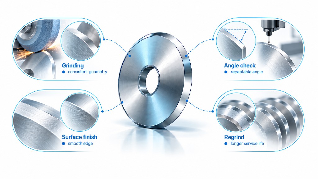
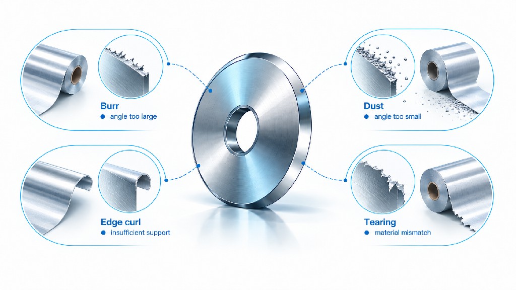
The following diagnostic map treats the bevel as one possible cause, not a universal explanation. A blade can be correctly manufactured and still fail in a poorly controlled process. Inspect the machine and the resulting slit before deciding whether to make a knife more acute or more supported.
| Observed defect | Possible bevel-related mechanism | Other causes to check first | Decision direction |
|---|---|---|---|
| Paper dust / fuzzy edge | Excessive post-cut contact or rounded primary edge | Overlap, side load, weak cut point, abrasive coating | Inspect tip; trial relief after setup is stable |
| Film whitening / stretching | Excess material displacement from thick wedge | Tension, knife speed, dullness, web path | Evaluate lower-drag geometry and edge quality |
| Adhesive pickup | Large rough contact area behind tip | Adhesive chemistry, temperature, cleaning interval | Consider polishing or suitable relieved profile |
| Repeated knife chipping | Local tip too weak for loading | Blade collision, runout, impact, brittle grade | Correct mechanical fault; then reassess support |
| Foil curl or microscopic burr | Asymmetric displacement or damaged edge | Lower knife, alignment, tension, side force | Inspect paired geometry and side faces |
| Metal coil burr growth | Edge rounding or inadequate support | Clearance, penetration, material grade, shafts | Measure burr and review cutting recipe |
| Uncut textile fibers | Edge fails to concentrate force consistently | Wrong slitting method, insufficient support, tension | Confirm mechanism before changing angle |
| Slit-width wandering | Asymmetric force or unstable knife body | Arbor fit, spacers, bearings, web guide | Correct machine geometry and knife orientation |
As a general rule, sudden defects following a collision, maintenance event, or roll change are more likely to call for an installation and condition inspection than a wholesale redesign of the nominal bevel angle. Slowly increasing dust or burr with running time may indicate wear progression. The GUANG CHUAN knife resharpening and replacement guide can help distinguish a regrindable edge from structural damage.
A good request for quotation reduces both production risk and repeated clarification. GUANG CHUAN manufactures custom machine knives and can review dimensional drawings or existing samples. For a geometry-sensitive slitting application, provide the working conditions along with the part dimensions. A quotation based on only outer diameter and bore size may omit the most important details of the edge.
| RFQ information | Recommended detail | Why the supplier needs it |
|---|---|---|
| Machine and cutting mechanism | OEM/model; shear, razor, score, or coil rotary shear | Prevents an unsuitable blade design |
| Knife role and orientation | Upper/lower, working face, left/right orientation | Ensures correct shear-face position |
| Dimensions | OD, ID, thickness, bore, keyway, mounting features | Ensures fit and structural compatibility |
| Bevel drawing | Included or single-face angle, datum, land width, relief, tip condition | Prevents ambiguous grinding instructions |
| Blade material | Grade, heat treatment, hardness acceptance, coating if any | Matches edge support and wear duty |
| Quality requirements | Flatness, runout, parallelism, finish, edge inspection | Supports repeatable cut-point geometry |
| Substrate | Material grade, full laminate structure, thickness range | Reveals fracture and abrasion behavior |
| Operating conditions | Line speed, tension, side load, overlap or clearance, duty cycle | Defines actual working stresses |
| Commercial requirements | Quantity, delivery timing, spare sets, regrind expectations | Enables realistic lifetime-cost comparison |
| Failure evidence | Photos of cut edge and worn knives; accepted defect limit | Identifies problems the new geometry must solve |
A drawing should also state its units, revision level, critical datums, and any measurement method necessary to accept the bevel. If dimensions come from an old sample rather than the machine OEM, make that clear; samples can be worn, reground, distorted, or modified. Where a customer supplies an existing knife, measure it at several circumferential positions before treating one local reading as the intended original specification.
For relevant manufacturing options, examine the paper-converting top and bottom slitter knife page and metal-coil rotary knife product page. The company's manufacturing and customization overview provides further background. Individual tolerances and geometry should always be confirmed in the accepted drawing and quotation rather than assumed from a general product-page example.
Knife purchase price is only one cost. A bevel that fails early can generate scrap, cleaning labor, sharpening expense, lost production, and repeated operator intervention. On the other hand, a premium design with a complex compound grind may not be economical if the existing basic blade already completes the required campaigns without quality loss. Buyers should compare cost per accepted production hour or cost per accepted unit, not just cost per knife.
One simple accounting model is: total cycle cost = blade purchase price + sharpening charges + intervention costs + defect-related cost. Then divide by total accepted productive hours across the defined knife lifecycle. The comparison must use the same quality requirements, equivalent substrates, and consistent definitions for changeovers and productive time. A longer-lived design is not financially better if it introduces damaging defects or unsafe operating risk.
The following figures are hypothetical planning assumptions only. They are not measured production data, published market averages, or GUANG CHUAN selling prices. They illustrate how the arithmetic works when one profile survives longer per acceptable campaign.
| Illustrative cost item | Profile A: basic design | Profile B: optimized relief |
|---|---|---|
| Initial knife purchase | $180 | $240 |
| Sharpening events within lifecycle | 2 | 2 |
| Cost per sharpening | $35 | $45 |
| Qualified operating campaigns | 3 | 3 |
| Accepted cutting hours per campaign | 12 h | 18 h |
| Total accepted cutting hours | 36 h | 54 h |
| Intervention cost per campaign | $80 | $80 |
| Defect-related cost per campaign | $15 | $10 |
| Calculated total lifecycle cost | $535 | $600 |
| Calculated cost per accepted hour | $14.86/h | $11.11/h |
For Profile A, the calculation is $180 + (2 × $35) + (3 × $80) + (3 × $15) = $535. The hourly cost is $535 / 36 = $14.86. For Profile B, it is $240 + (2 × $45) + (3 × $80) + (3 × $10) = $600, or $600 / 54 = $11.11 per accepted hour. Profile B costs more initially, yet is cheaper per accepted hour under these assumptions. The example does not establish that compound blades generally increase life by 50% or produce these savings in real lines.
It is often useful to track the actual reason a knife is retired. If a blade is discarded because it chipped after an accidental collision, that event should not be misinterpreted as normal bevel wear. If the knife can be reground, keep the new profile, remaining diameter, and reduced edge land within the accepted engineering limits. The resharpening versus replacement guide provides a structured maintenance perspective.
There is no single angle that fits all paper grades and slitting systems. A published Valley Grinding illustration identifies a 45° profile as common for paper, but it is one defined knife geometry rather than a universal prescription. Tissue, coated stock, lightweight paper, and board differ in fiber behavior and abrasion. Use a correctly referenced profile as the starting point, then compare dust, fibers, edge quality, and life on the actual machine.
A more acute ideal wedge can penetrate with less geometric displacement in some conditions, but its tip may be less supported. The real edge also has a finite radius, local grinding marks, and possible microchips. A very acute blade that chips rapidly may perform worse than a slightly stronger edge with a properly designed secondary relief. Select for qualified output and safe, predictable durability rather than the smallest advertised number.
In commercial descriptions, both phrases can refer to the ground cutting profile. Neither is a complete drawing specification by itself. Ask whether the number describes an included tip angle, a single ground face, or a secondary relief. Also distinguish these terms from the knifeholder cant angle, which is a machine alignment parameter rather than a ground profile.
The answer depends on the required working shear face, material behavior, and holder design. A single bevel can provide a defined reference face and robust geometry. A double or compound profile can reduce contact after separation in suitable converting systems. The exact meaning of “double bevel” varies among catalogs, so a cross-sectional drawing is essential. Do not assume that a symmetric V-edge is interchangeable with a compound shear-slitter top knife.
Choose a candidate based on film thickness, orientation, coatings, laminate structure, cutting mechanism, and customer quality limits. A fine and well-relieved edge can help limit drag, but its support, finish, and the machine's tension and engagement must also be correct. No single included-angle range can be responsibly guaranteed from the word PET alone. A matched sample trial is the preferred purchasing method.
Some knife families are versatile across several thin-web applications, but broad material coverage is not equivalent to universal geometry. Foil may demand exceptionally consistent cut-point control; paper may be limited by dust; film may stretch; and metal coil uses different shear mechanics and higher local loads. Always check both the cutting process and the tool drawing before attempting interchangeability.
Well-designed compound and double-bevel profiles can reduce contact and dust in many converting applications, as described in DIENES literature. However, dust also responds to blade wear, paper coating, cut-point settings, side force, and runout. A poor double bevel can produce more dust than a well-maintained single-bevel knife. Evaluate equal cutting lengths under controlled conditions.
Only with engineering approval. A regrind changes the edge profile and possibly the outer diameter, primary land, or working face location. On a matched shear pair, altering a profile can affect the cut point and clearance assumptions. Restore the drawing-approved geometry unless the machine owner has validated a new revision and verified adequate remaining knife dimensions.
Sharpness is only one factor. The bottom knife may be worn, the clearance may be wrong, the holder may be misaligned, or the material properties may have changed. In metal coil cutting, burrs are linked to deformation and fracture behavior across the complete shear system. Check the installed geometry and measured defect pattern before purchasing a more acute blade.
Show the cross-section at the correct cutting-edge location, state whether the number is an included angle or a face angle, identify the datum and working face, and specify any primary land, backing relief, hollow shape, or edge radius. Include tolerances and an inspection method that the supplier can actually use. The drawing should also state material grade, thickness, bore, runout, and other critical dimensions.
Not necessarily. An existing geometry may work well in a different tool steel, but achievable tip support and chipping behavior can change with metallurgy and heat treatment. When comparing steel grades, keep the bevel consistent if technically feasible. If the new material requires a changed edge design, treat it as a complete tool-system trial and document the difference.
Send the drawing or a good sample, machine model, upper/lower knife role, substrate and thickness range, operating conditions, current blade material, quality problems, target edge specification, and required quantity. Photos of the cut edge and worn blade are especially helpful. If the existing knife is already successful, provide its profile as a controlled reference rather than starting from a generic catalog angle.
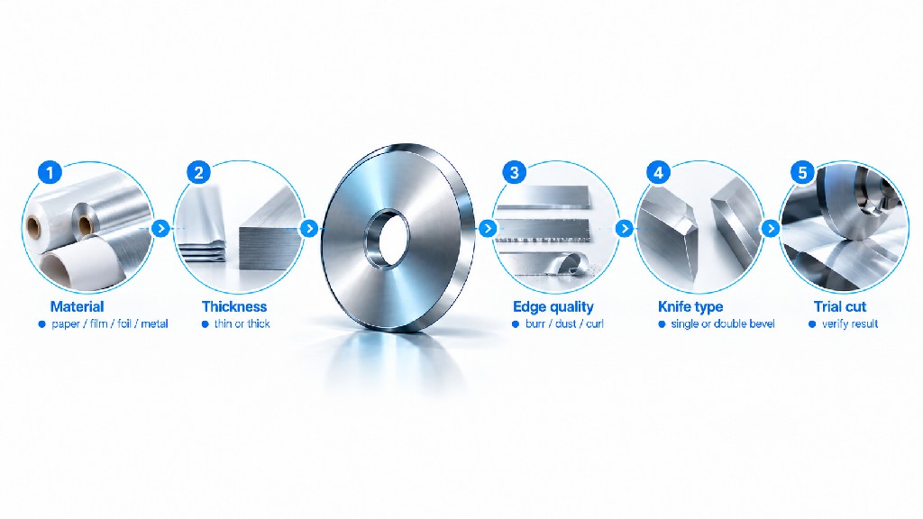
Choosing a reliable slitter knife bevel angle is an engineering decision supported by a repeatable cutting test. It begins with the right cut method, a clearly defined angle convention, and a profile that balances clean separation with sufficient tip support. The final purchase should reflect measured edge quality, life between interventions, manufacturing consistency, and total operating cost—not a single angle copied from an unrelated application chart.
Need a custom slitter knife profile or replacement quote? GUANG CHUAN manufactures industrial blades to suit application-specific drawings and samples. Share the machine model, knife dimensions, a sketch of the current bevel, substrate thickness and composition, operating speed, and photos of the defect. We can discuss a suitable geometry for the stated cutting duty and provide a quotation based on the confirmed requirements. Contact GUANG CHUAN for a technical quotation, or review our paper-converting knife configurations and coil-slitting knife options before sending your specification.
Technical disclosure: Published numerical design examples are attributed in context to the named industrial sources. All geometric calculations and lifecycle cost examples are explicitly identified as computed or hypothetical. Material-specific recommendations in this guide are engineering screening considerations, not certified universal angle standards, guaranteed life claims, or substitutes for OEM safety procedures.

Leave A Message
Scan to WhatsApp :

 English