




A slitting line can have sharp rotary knives, correctly machined spacers and an experienced operator—and still produce paper dust, feathered film edges, irregular foil slits or premature blade wear. Sometimes the missing adjustment is only a fraction of a millimeter: slitter knife overlap. Sometimes the problem is that the operator changed overlap to compensate for a completely different fault, such as excessive side force, loose bearings or unstable web tension.
In rotary shear slitting, the upper and lower knife edges must establish a stable cutting point. They generally need a small, controlled amount of geometric engagement, but more overlap is not automatically a stronger or cleaner cut. Excess engagement increases the distance a moving web travels against the knife bevel, promotes friction and can change the cutting point. Too little engagement risks interrupted cutting or the upper blade climbing onto the lower knife. The right setting depends on the knifeholder, knife diameters, web path, material, side-load system and allowable operating movement.
This guide is for converters, OEM machine builders, maintenance engineers and buyers specifying upper and lower slitter knives. It explains the difference between vertical overlap and horizontal clearance, presents published manufacturer reference values, works through measurement methods, and offers a repeatable trial procedure. It also separates thin-web shear slitting from metal-coil slitting, where the word penetration may describe a different physical quantity.
The practical answer: Start with the machine or knifeholder OEM's approved overlap range and the proven recipe for the exact material. If no validated recipe exists, use a source-appropriate reference range only as a trial starting point. Select the least stable engagement that produces a complete, acceptable slit throughout the full operating condition, while keeping sufficient margin for runout, deflection and holder movement. Confirm the result through edge inspection, particle or burr measurements, dimensional checks and a documented production trial—not by the depth dial alone.
For the broader relationship among blade geometry, clearance and side load, see GUANG CHUAN's circular slitter knife clearance, overlap and side-force setup guide. This article concentrates on overlap itself: how much is needed, how to measure it and how to prove a setting is stable.
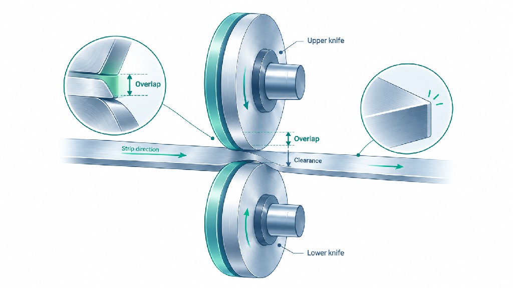
Slitter knife overlap is the signed geometric engagement between a rotary upper knife and its lower knife or anvil ring in the engaged cutting position. In a common tangential shear-slitting arrangement, it is the distance by which the upper knife's outer cutting edge passes below the tangent at the top of the lower knife. The same dimension may be called vertical overlap, blade overlap, cutting depth, or—somewhat ambiguously—slitter blade penetration.
Imagine two circles representing the projected cutting edges of the upper and lower rotary tools. If they merely touch at one tangent point, the geometric overlap is zero. Move the upper knife toward the lower knife until their projected circles intersect and the upper edge extends beyond the lower tangent: the positive offset is the overlap. The knives are not meant to crash edge-on-edge; their axial alignment, cant angle and side loading determine where the two shear faces meet. On some arrangements, the blades are separated axially and their projected circumferences overlap without the edges occupying the same physical plane.
The definition sounds simple, but drawings are often misunderstood. The measurement direction must be specified, normally along the machine's vertical engagement axis or along the common centerline of the two knife circles. A reading from a holder's adjustment knob is not necessarily the actual edge-to-edge overlap. Unless the machine has a verified reference datum, the knob shows travel, not an independently measured engagement depth.
The industrial slitting specialist DIENES defines overlap as the distance the top knife extends below the lower knife's tangent. That definition is especially useful for discussing tangential web converting. The equipment manufacturer's drawing remains authoritative for machines that use a different orientation, measurement datum or mechanically linked knifeholder design.
The upper or male knife is commonly a beveled or dished circular blade mounted in a holder. The lower or female knife may be an anvil ring, a grooved ring or one element of a multi-knife shaft assembly. The moving web passes through a region where the edges act like rotary scissors. The desired result is controlled separation at a repeatable cutting point, with limited unwanted contact between the material and the knife body.
Three different concepts must remain separate. Geometric overlap tells you the vertical engagement of the two circles. Cutting-point stability tells you whether their functional shearing relationship remains in the intended position under speed and load. Material penetration or fracture depth describes what happens inside the substrate itself. A knife can be geometrically engaged by 1.0 mm without literally cutting 1.0 mm into a film that is only 20 micrometers thick.
This distinction matters when reading supplier catalogs. One catalog may specify a 1.0 mm overlap for a paper-winder holder; another may refer to 20% penetration for a metal coil undergoing plastic deformation before fracture. Both numbers can have meaning, but they cannot be compared or substituted without first establishing the measurement definition.
Not every circular blade system has an upper/lower overlap setting. Razor slitting passes a thin sharp blade through a supported or unsupported web. Score, also called crush cutting, presses a wheel against an anvil roll. Rotary shear slitting relies on two interacting cutting edges. A razor's insertion depth or a score wheel's loading force should not be copied into a shear knife recipe.
As DIENES explains in its shear-cut overview, paired overlapping knives serve a wide variety of paper, board, labels, film, foil, nonwoven and related converting applications. The method is versatile precisely because the tools, holder design and geometry can be adapted. Versatility does not imply one setting is correct for every substrate.
| Term | What it describes | Typical measurement | Common setup mistake |
|---|---|---|---|
| Vertical overlap | Geometric engagement of upper and lower cutting-edge circles | mm or inches; datum defined on drawing | Treating an adjustment-knob movement as true overlap |
| Horizontal clearance | Lateral gap between shear faces, where a clearance-type system uses one | mm or % of strip thickness, by definition of the system | Applying a metal-coil gap formula to a contact-loaded web knifeholder |
| Side load | Lateral contact force imposed by a holder | N, lbf or a validated force-gauge method | Confusing regulator pressure with actual cutting-edge force |
| Cant or shear angle | Deliberate angular relationship at the contact point | Degrees | Increasing overlap to hide incorrect cant |
| Runout | Radial or axial deviation as knife rotates | Total indicator reading at a stated surface | Measuring a loose, unmounted blade instead of the assembled tool |
| Material fracture penetration | Depth of deformation or burnished zone before separation | Length or % of material thickness | Calling this the knifeholder's geometric overlap |
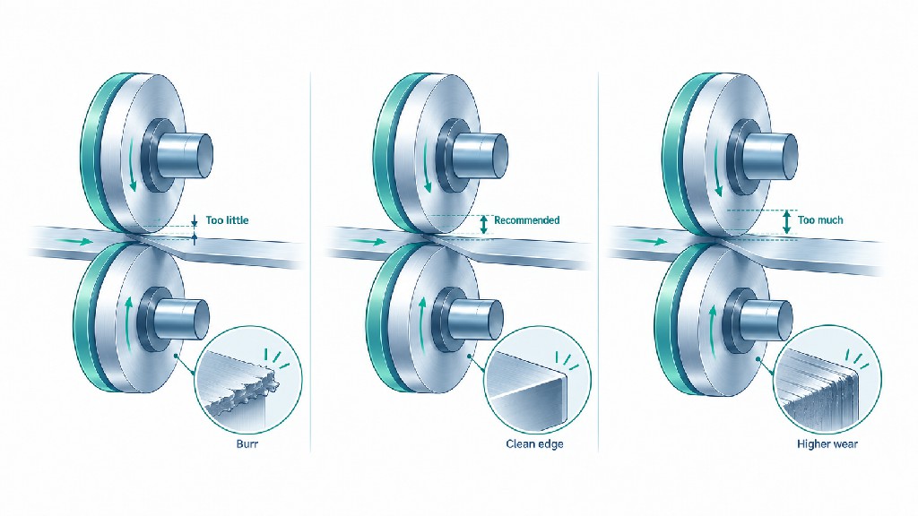
Overlap is not simply a clearance for two parts to cross. It influences where the cut begins, the path taken by the web near the bevel, the amount of rubbing and the system's resistance to disturbances. Those changes affect both visible slit edges and less obvious costs such as dust removal, cleaning frequency, regrinding, web breaks and unplanned downtime.
In a tangential web arrangement, the web should separate at a narrow, controlled location near the lower knife. When the top knife is set too deep, the material may remain in contact with its bevel over a longer travel path. This is the travel chord discussed in shear-slitting literature. A longer contact path can increase friction and scuffing even if the final material is completely separated.
The effect is not merely theoretical. In its technical discussion of dust caused by incorrect overlap, DIENES reports that, for the geometry used in its example, 0.020 in of excess overlap increased travel-chord length by 41%. Its example with a further 0.060 in excess reports a chord-length increase of 102%. These are manufacturer-published geometric examples, not universal dust-generation percentages or predictions for every blade diameter. The important physical lesson is that a seemingly modest additional engagement can produce a disproportionately longer contact path.
Cut quality can therefore deteriorate while the knives still appear to be cutting decisively. On paper the evidence may be fibers and dust. On adhesive stock it may be coating buildup or edge debris. On film it may be localized stretching and fine strand formation. A converter chasing incomplete cuts by repeatedly adding depth may eventually trade one defect for another.
If the upper knife does not reach the designed cutting position, the material may not encounter a continuous functional shear point. The result can be intermittent uncut bridges, ragged fibers, inconsistent edge appearance or a slit that becomes unreliable when production speed rises. Runout, elastic shaft deflection, holder compliance or fluctuating web tension may make a marginal setting fail once every revolution or only on certain lanes.
A serious failure mode is knife jump: the top knife lifts or travels onto the upper surface of the lower knife rather than maintaining its intended relationship. This can chip or destroy cutting edges. Both DIENES and Valmet's winder adjustment guidance warn that insufficient engagement can produce destructive contact or an incomplete slit. Increasing overlap may be justified after the cause has been diagnosed, but no operator should deliberately force a defective holder or unstable shaft to run by adding large, uncontrolled depth.
Excessive overlap generally increases the chance that more of the blade bevel or body contacts the material. The extra interaction may produce dust, heat, friction marks, foldover or a change in the effective cut point. It also raises the risk of poor interaction between knife surfaces, especially if cant or side force is incorrect. Wear may appear on a face where only a small, controlled contact region should have been present.
More depth is particularly tempting when a line starts producing fuzzy edges after a knife change. Yet if the new blade diameter differs from the previous diameter, the existing holder scale may be wrong. If the real problem is a chipped lower ring, side-force error or poor winding tension, added overlap will not cure it. It can accelerate damage and obscure the original cause.
Use a restrained diagnostic principle: first establish that the knives, holder, bearings, web path and side relationship are mechanically sound; then adjust overlap in controlled, traceable increments within the OEM envelope. Change one variable at a time. If a trial shows that more engagement improves continuity but substantially increases debris, investigate whether the holder or support system is moving under load before accepting the deeper setting.
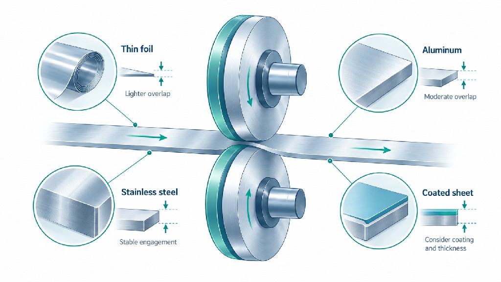
There is no universal millimeter value or fixed percentage of web thickness that governs all rotary shear slitters. The proper range is specific to machine geometry, knifeholder construction, material and operating condition. Published numbers are useful when their original context is preserved. They should be treated as reference points for a trial, not as independent permission to override the equipment manual.
The following table preserves the context of two prominent equipment sources rather than blending their values into a fictitious all-industry standard. Conversions use 1 in = 25.4 mm, rounded for readable setup planning. The machine supplier's figures and instructions take priority over any editorial table.
| Published context | Original overlap guidance | Approximate metric equivalent | How to interpret it |
|---|---|---|---|
| DIENES, general shear-slitting discussion | 0.030–0.040 in | 0.76–1.02 mm | Manufacturer's general guidance for many of its discussed applications; not a universal specification |
| Valmet, tissue grades on its referenced winder slitters | Less than 0.030 in | Less than 0.76 mm | Grade-specific guidance for the equipment configuration discussed |
| Valmet, printing papers | Approximately 0.030–0.050 in | Approximately 0.76–1.27 mm | Validate blade geometry, grade and chord gauge |
| Valmet, light or coated boards | 0.050–0.060 in | 1.27–1.52 mm | Larger overlap may be used on those named winder applications |
| Valmet, boards and liner papers | 0.060–0.080 in | 1.52–2.03 mm | Specific to the listed paper grades and system |
The DIENES value comes from its shear-slitting setup discussion. The paper-grade figures come from Valmet's published slitter adjustment instructions. Valmet also describes using a chord gauge suited to the system, highlighting that a published depth and the practical measurement tool must be considered together. Published examples from different OEMs need not agree: their holders, diameter combinations and web paths may not be the same.
These references support an important conclusion. A tissue winder may require shallower engagement than a board winder, but that does not imply that basis weight alone determines depth. Knife diameter, edge profile, blade support and the lower anvil arrangement remain necessary inputs. If a supplier recommends an overlap outside these examples, request the intended holder drawing and trial evidence rather than declaring the number wrong solely because it differs from a table.
Thin films, metallized webs, laminated structures and adhesive labelstock can be sensitive to additional contact and drag. Some manufacturers publish informal starting ranges around 0.5–1.5 mm for selected thin-web shear systems; for example, Maxwell's paired-knife setup guide separates film/foil from heavier paper and nonwovens. Those figures are supplier-specific indicative ranges, not an ISO or ASTM setting standard. A packaging converter should not transfer a paper-winder figure blindly to a battery-foil station, nor assume that every knifeholder can reliably work at an arbitrarily small engagement.
A better sequence for a delicate material is to verify its actual construction, required cleanliness and edge quality, and then locate the machine OEM's minimum stable overlap with a modest operating margin. Check the incoming web for gauge variation, waviness and splices. Establish whether contact is controlled by pneumatic side loading, a fixed spacer stack or another mechanism. The same nominal 25-micrometer film can behave differently after coating, metallization or lamination.
For paper, grammage is not thickness. ISO 536:2019 specifies a method for grammage, whereas ISO 534:2011 concerns paper and board thickness, density and specific volume, with stated exclusions. Those standards characterize materials; neither specifies a knife overlap. For thin plastics, ASTM D882 concerns tensile properties of thin sheeting, again not rotary knifeholder depth. Material tests can inform a trial but do not replace cutting validation.
When answering “how much overlap?”, ask four sequential questions. First, is this a web shear slitter or a metal strip/coil slitter? Second, what does this machine call overlap and from which datum is it measured? Third, what is the approved adjustment window for the actual knife diameters and holder? Fourth, what is the smallest setting that passes the defined quality criteria with adequate dynamic margin at production speed?
If the answers are unknown, the most defensible starting point is not a number from a search result. It is an equipment drawing, previous successful job record, controlled engineering trial or consultation with the knifeholder manufacturer. An operator who documents 0.9 mm engagement, an acceptable dust level and stable performance across several rolls has more useful process knowledge than one who simply repeats “always use 1 mm.”
A useful setup sheet must translate “move the upper knife slightly lower” into a measurable, reproducible dimension. That requires identifying the correct reference surfaces and deciding whether to measure overlap directly, infer it from known centers and radii, or use a chord-based gauge designed for the holder. Whichever method is chosen, the result should be checked with the knives mounted as they actually run.
On equipment designed for direct measurement, establish the reference tangent of the lower knife or anvil ring, then measure how far the upper knife's cutting circumference extends beyond it in the engaged position. Use the dedicated depth gauge, certified setting tool or OEM procedure. The reading is the geometric overlap only when the two datum surfaces represent the actual cutting edges and the gauge is aligned in the prescribed direction.
Clean the contact surfaces before measuring. A tiny adhesive deposit, nicked gauge point or incorrectly positioned ring may be comparable in size to the adjustment itself. A reading should also specify whether the holder is in its loaded cutting position; some pneumatic holders move axially and vertically during their engagement sequence. A measurement made while the holder is retracted may have little relationship to the running geometry.
Valmet's instructions describe applying a purpose-made chord gauge to the lower band for its winder configuration. An OEM-specific tool is often more reliable than improvising with a steel rule because the gauge is designed around the geometry and access of that knife station.
For a simplified pair of circular cutting edges with aligned centers in a common radial plane, define R₁ as upper-knife radius, R₂ as lower-knife radius and C as center-to-center distance measured along their common centerline. The signed radial engagement can be expressed as:
Overlap O = R₁ + R₂ − C
Positive O means the projected cutting circles intersect; zero means they are tangent; negative O means a separation remains. This geometric expression is a calculation aid, not an instruction to operate intersecting blades in the same axial plane. Real shear knives incorporate specified lateral positioning, cant and edge form. For offset centers or noncircular tools, use the applicable OEM drawing instead.
Illustrative calculation: Suppose an upper knife has an outside diameter of 100.00 mm and a lower anvil ring has an outside diameter of 150.00 mm. Their radii are therefore 50.00 mm and 75.00 mm. If the distance along the common centerline is 124.00 mm, the calculated overlap is 50.00 + 75.00 − 124.00 = 1.00 mm. This describes the nominal geometry; it does not predict finished slit quality.
| Illustrative dimension | Value | Meaning |
|---|---|---|
| Upper outside diameter | 100.00 mm | Nominal projected cutting-edge circle |
| Lower outside diameter | 150.00 mm | Nominal anvil cutting-edge circle |
| Upper plus lower radii | 125.00 mm | Tangency reference before considering center spacing |
| Measured center distance | 124.00 mm | Common-centerline separation |
| Calculated overlap | 1.00 mm | Nominal positive engagement |
Now imagine the upper knife is reground from 100.00 mm OD to 98.00 mm OD. Its radius has decreased by 1.00 mm. If the center distance is not changed, the calculated overlap becomes 49.00 + 75.00 − 124.00 = 0.00 mm. To recover a 1.00 mm geometric overlap in this simplified arrangement, the centers would need to be brought to 123.00 mm. This example is particularly useful for explaining why replacing one blade with a different diameter can change the real engagement even when the depth-scale setting is untouched.
A machine might not have sufficient safe travel to restore that engagement. The minimum usable blade diameter, holder extension limit, guarding and approved regrind allowance must therefore be checked before a worn knife is returned to service. Do not infer that any amount of diameter loss can be compensated by moving the holder.
Where the projected upper and lower circles intersect, their geometry defines a chord. A chord measuring tool may relate a distance across the intersecting region to the target overlap. The measurement can be convenient when a direct vertical depth gauge cannot reach the cutting point. However, a given chord length is not equivalent to a universal overlap; the relationship varies with the radii of the two tools and the alignment of their centers.
If an operator changes from a 90 mm upper knife to a different diameter, the old chord indication or setting chart may no longer apply. Use the holder manufacturer's gauge or conversion table for the actual pairing. A supplier's generic statement that “the chord should be X millimeters” is incomplete unless the upper and lower diameters and gauge geometry are supplied.
Record both the target and measured overlap, including units, measurement method, equipment identification, upper/lower diameters after any regrind, gauge identification, and the authorized setup state. If measurement uncertainty is significant compared with the requested adjustment, do not claim more precision than the instrument supports. A shop-floor dial showing two decimal places does not prove the installed knife edge is controlled to 0.01 mm.
For critical converting applications, consider checking the fully assembled system for radial and axial runout. Measure at several rotation positions and note where the maximum and minimum engagement could occur. The goal is to understand the range of engagement, not merely one static number. A setting that measures 0.8 mm at the best rotational position but suffers a substantial dynamic loss at another position can fail intermittently.
Two lines with identical nominal overlap can produce completely different edges. Their top knife profiles, lower ring shapes, holder stiffness and web support may vary. The phrase upper lower knife overlap therefore belongs in a complete mechanical specification, not a single unchecked setup box.
A dished or beveled knife presents a narrow cutting edge while keeping much of the blade body away from the material. Its bevel angle, hollow grind, thickness, dish and surface finish affect the contact area as overlap increases. A blunt knife may need more force to complete a cut, but this is not evidence that a deeper setting is the correct repair. Inspect and regrind the edge to its specified profile when warranted.
The outer diameter matters because it determines how a commanded holder position translates into engagement. The edge location after regrinding should be measured, not assumed from a product label. For replacement tool selection, GUANG CHUAN's circular slitter knives selection guide discusses how blade dimensions, geometry, bore fit and machine conditions affect performance. Matching outside diameter alone is not a complete knife compatibility check.
The bottom knife can be a flat anvil ring, a grooved multi-edge ring or a stacked group of rings on a driven shaft. The relevant datum is its actual working edge, not an adjacent shoulder or spacer face. Worn lands, chipped ring edges and incorrect groove pitch can all make an overlap reading misleading. In multi-lane slitting, one incorrectly positioned groove may create a defect on only one of several otherwise acceptable strips.
GUANG CHUAN describes multi-groove, multi-edge lower slitter knives for applications including paper, foil and composite substrates. Before ordering such a part, specify active cutting-edge locations, groove pitch, land widths, runout references and how the knife will be mounted. The cutting geometry must match the actual holder and slit pattern.
In many web-converting shear knifeholders, a spring or pneumatic mechanism maintains the side contact that makes the upper and lower edges act like scissors. Setting overlap deeper cannot correct a holder that fails to maintain its required lateral force. Conversely, excessive side loading can rub and wear the edges prematurely even at nominally correct overlap.
A regulator pressure is not the same as a measured force at the knife. Piston size, linkage geometry, friction and mechanical preload affect the conversion. The actual appropriate contact depends on the machine. Valmet publishes pressure and force guidance for particular winder applications, but those values are not transferable to a different pneumatic cartridge merely because both are called shear slitters.
Avoid an especially common shortcut: tightening side load and increasing overlap at the same time. If the edge improves, the team will not know which change helped; if wear accelerates, the cause is equally uncertain. Establish proper mechanics first and use single-variable tests afterward.
The cant angle sets a small intentional difference in orientation so the two edges have controlled contact near the desired shear point, rather than rubbing over a broad face. Depending on the design, the angle may be built into the holder or adjustable. The DIENES discussion of shear-cut geometry notes that a small angle, commonly around one-half degree in its examples, can be appropriate, but alternative angles are used for different materials. That is contextual guidance, not permission to modify a fixed-angle holder.
Too little effective cant can produce a wider rubbing contact zone, while an unsuitable angle may affect edge quality and wear. Overlap, side force and cant interact. If cut quality is poor after replacing one knife, compare the holder's actual orientation to the OEM specification before trying a large overlap increase.
A well-measured static overlap can still be too small if the blade moves during rotation or the knife shaft deflects under a web or coil load. Causes include worn bearings, dirty mating faces, eccentric bores, shaft bending, incorrect clamping, thermal change and vibration. The correct response depends on the source. Adding depth may temporarily prevent an incomplete cut, but it can also overload other parts and shorten knife life.
Consider a purely illustrative engineering margin, not an OEM tolerance: a nominal 0.80 mm overlap may be reduced by 0.10 mm due to combined positional variation and by another 0.10 mm due to an adverse loaded deflection at one operating condition. The working engagement in that worst-case illustration becomes 0.60 mm. Those assumed variations must be verified, not copied into a machine specification. A conservative recipe is one in which the measured dynamic minimum engagement still produces continuous cutting, while the maximum engagement does not create unacceptable contact.
| System factor | What to inspect | What a change may look like at the slit edge |
|---|---|---|
| Upper/lower knife OD | Actual diameter after regrinding; matching knife sets | Several lanes change behavior after tool replacement |
| Mounted runout | Edge TIR and seating condition by a stated datum | Periodic marks or partial cuts once per revolution |
| Holder stiffness | Slide play, bearing condition, lock mechanisms | Cut becomes unstable as speed rises |
| Side load | Approved regulator setting and measured force method | Rubbed edge, wear, intermittent scissor contact |
| Cant angle | Fixed holder specification or qualified adjustment | Local rubbing, dust, edge deformation |
| Web guidance | Entry/exit roll position, flutter and wrap path | Defects linked to tension or tracking variations |
| Knife edge | Chipping, bluntness, bevel and face damage | Persistent one-sided defect after depth changes |
A tangential shear slitter and a wrapped-web slitter do not put the web against the lower knife in exactly the same way. In a tangential configuration, the web approaches a localized cutting region and departs toward an idler or rewind section. In a wrapped arrangement, the web contacts some arc of the lower knife or anvil, creating a larger set of possible cutting locations.
This matters because overlap changes the effective cutting point differently under the two layouts. In the DIENES explanation of tangential and wrapped shear-cut geometry, web tension and the stability of the cut point are essential to reliable edge quality. Low tension can permit flutter and repeated contact with the bevel; excessive tension can stretch or break the web. Moving the knife deeper without considering the web route can increase rubbing while failing to address the underlying instability.
For a tangential web, confirm the approach angle, lower-knife tangent and exit support. For a wrapped web, confirm the intended wrap contact and cutting position along the anvil circumference. Document the layout when requesting replacement knives, because the same nominal blade diameter and overlap can behave differently in the two arrangements. Web support near the cutting point may be as important as the choice between 0.8 and 1.0 mm of engagement.
A substrate name helps identify likely failure modes, but no material label by itself defines an absolute setting. A coated 80 gsm paper may be less forgiving of abrasive contact than an uncoated sheet of similar grammage; a heat-sensitive film may require attention to friction; a foil may require microscopy for tiny burrs. The objective is to choose a realistic inspection plan as well as a starting engagement.
For thin tissue, excessive bevel contact can produce fibers and dust that contaminate downstream rolls and equipment. The shallow values in Valmet's table are associated with its named winder conditions, and should be used with the intended gauge. Printing paper may tolerate a different overlap depending on furnish, moisture, ash content and operating speed. Coated stocks can shed coating particles in addition to fibers, so dust collection and inspection location must be consistent during a trial.
Record paper grade, grammage, caliper, moisture condition when relevant, line speed and blade history. Check both slit edges; a good edge on the operator side does not guarantee the far-side edge is acceptable. Rather than judging from a single freshly cut meter, examine the edge after a stable run and confirm that the amount of debris does not increase materially as the roll proceeds.
Board and some multi-ply structures may require a different knife profile, greater machine rigidity or a holder with more usable adjustment travel. Larger engagement references for Valmet board grades are not proof that “thicker always means deeper.” The correct relationship depends on stiffness, layer bonding and whether the substrate compresses or delaminates at the cutting point.
Pressure-sensitive adhesive labels and tapes add another complication: deposits on the knife face can alter friction and effective clearance during a run. A deeper overlap may increase the area on which adhesive accumulates. Inspect cleaning and release practices, knife finish, temperature and the adhesive formulation. GUANG CHUAN offers circular slitting blades for BOPP and masking-tape rolls; their compatibility must still be checked by machine model, diameter, arbor fit and cutting method rather than by application name alone.
For polymer film, a poor setting may show as feathering, edge stretch, wrinkles, wandering slits or fine angel-hair strands. A laminate may also delaminate near the cut if layer properties or adhesive bonding are unsuitable. An excessively deep knife can drag over the web even when the edges eventually separate. An insufficient or unstable overlap can permit partial cuts on localized thicker sections or at splices.
Start by checking film gauge, structure, web tension and support. Verify the intended side contact and whether the knifeholder has a controlled depth adjustment. Inspect at steady production speed, not only at crawl speed. Surface scratches or edge deformation may emerge at higher speeds because friction, dynamic motion and winding conditions change. For particularly delicate structures, a different slitting process may deserve evaluation rather than endlessly changing one shear setting.
Metallic foils raise concerns about minute burrs, loose particles and edge damage that can affect downstream operations. Correct overlap must be considered together with edge condition, substrate temper, line cleanliness, tension and the lower-knife relationship. The acceptance criteria may be much tighter for a specialized electrical product than for ordinary flexible packaging.
Do not assume the correct settings for a paper winder can be applied directly to foil, even where both use paired circular knives. Microscopic inspection of both edges, sampling after sustained operation and a documented defect limit are more useful than a generic promise of “zero burr.” If a defect repeats around the circumference, check edge chipping and mounted runout. If it appears only after long running, inspect heat, buildup and bearing movement.
Nonwovens and textiles may fail by fiber pullout rather than a neat continuous crack. Fibrous products also vary by bonding pattern, basis weight, density and orientation. A single overlap setting may be satisfactory on one nonwoven and create a hairy edge on another. Before changing depth, verify knife sharpness, web tension and the supported cutting location. Some materials require a distinct holder, special edge geometry or another slitting method.
For multilayer products, the interface between layers matters. A cut can appear clean on the surface while leaving a partly connected internal layer. Use a simple separation test on the full laminate cross-section and inspect both edges after rewind. If added overlap improves layer separation but creates unacceptable debris or heat, consider changing the blade profile, improving web support or using a different process rather than accepting the new defect.
Metal coil slitting frequently uses upper and lower arbors carrying knives and spacers. It also uses the terms vertical clearance, overlap and penetration, but these can describe different things across equipment and publications. For a metal strip, the material first deforms under the knife edges. A burnished zone develops before the cracks propagate and meet, creating a fractured surface and possibly a burr. The depth of this material deformation is not the same thing as the geometric overlap of two circular knives.
Example: An engineering article may say that a metal strip penetrates to approximately 20% of its thickness before fracture. That percentage refers to the material's shearing behavior under specified conditions, not necessarily an instruction to set the upper knife edge 20% of strip thickness below the lower knife tangent. Likewise, a stack-style metal slitter may intentionally use positive, near-zero or even negative signed vertical overlap depending on material, knife configuration and machine engineering. The approved setting should come from that machine's setup method, not a universal web-converting reference.
An important companion variable is horizontal clearance, the lateral relationship at each shear plane. For a controlled-gap metal coil slitter, clearance is frequently expressed as a fraction of strip thickness and adjusted with reference to material properties. It would be a mistake to treat that fraction as overlap. A contact-loaded paper knifeholder may instead maintain near-contact between faces through side loading, making the metal-coil spreadsheet inappropriate.
| Metal-slitting term | Quantity being described | Why the distinction matters |
|---|---|---|
| Signed vertical overlap | Relative geometric position of upper and lower cutting circles | May be positive, zero or negative by system design |
| Horizontal knife clearance | Lateral spacing at each shearing plane | Strongly influences fracture, rollover and burr formation |
| Penetration before fracture | How far deformation or burnishing progresses in the strip | A material-response observation, not automatically a holder dial value |
| Knife/spacer stack pitch | Positions of knives, shims and strips on the arbors | Determines slit widths and affects whether edges align properly |
| Separator and stripper setting | Support and strip separation after cutting | Can create winding and edge problems despite correct overlap |
For a deeper discussion specific to coil defects, GUANG CHUAN's guide to reducing burrs when slitting metal coils addresses material condition, knife geometry and other causes of burr formation. The related rotary slitter knives for metal coil lines are an example of the tooling category; any proposed overlap must still be confirmed against the machine drawing and trial results.
Do not invent a universal metal-coil overlap chart from paper-winder data. Even within metal processing, low-carbon steel, harder stainless alloys, aluminum and electrical steel can require different clearances and knife strategies. Mechanical properties, actual thickness, edge acceptance criteria and machine stiffness matter. The quoted percentage must be labeled clearly enough that the purchaser knows whether it refers to lateral clearance, working engagement or a metallographic penetration zone.
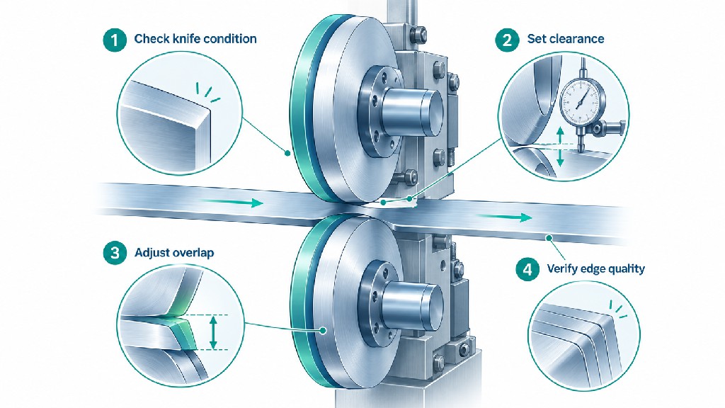
Good processes separate mechanical verification from production optimization. The checklist below is a planning framework for authorized personnel, not a replacement for the machine OEM's instructions. Powered slitters contain sharp rotating knives and stored pneumatic, electrical, hydraulic and mechanical energy. Setups and measurements require the correct isolation procedure and competent personnel. In applicable United States workplaces, OSHA's control-of-hazardous-energy rule, 29 CFR 1910.147, is a relevant regulatory reference; local rules may differ.
Record the substrate, thickness or grammage, lot, coating, width, slit pattern, operating speed, winding conditions and the exact knifeholder model. Establish what “clean slit” means for this customer: perhaps no visible feathering under agreed magnification, a burr below a specified measured limit, no delamination, or a particle result below a negotiated acceptance threshold. The team should identify the sampling method and inspection location before adjusting the depth. Otherwise different shifts may accept different edges.
Gather the last successful recipe, equipment manual and records of tool changes. Identify whether the current blade set was reground, whether the lower anvil was changed, and whether any web-path or tension settings were altered. A recipe from a similar machine may be a useful hypothesis but should not be treated as approved on a different holder.
Stop the line and follow the OEM's lockout, verification and blade-handling procedure before accessing the shearing zone. Ensure stored energy is controlled and rotating elements cannot move unexpectedly. Never test the knife gap by touch, attempt to stop a spinning blade with a hand or measure inside an unguarded moving nip. If an OEM-specific overlap measurement requires a particular engaged or loaded state, only authorized staff should establish that safe state according to the written procedure.
Inspect both knife edges for chips, burrs, corrosion, contamination and the correct bevel. Look for defects in the holder bearings, slides, clamps and seating shoulders. Confirm the lower knife has no loose mounting or obvious runout. Repairing a mechanical defect may restore an acceptable cut without any increase in overlap.
Measure or verify the installed upper and lower outside diameters, especially after regrinding. Confirm bore fit, shoulder contact, axial orientation and the active lower edge. Where applicable, check a matched set of upper knives rather than assuming mixed-diameter blades will produce identical engagement across a wide shaft. Verify the available vertical travel against the OEM's minimum knife diameter and adjustment limits.
Record the gauge or machine reference point. An overlap figure without its datum is difficult to reproduce. If the operator interface shows a position number rather than physical millimeters, note that distinction and keep the conversion from the equipment manufacturer rather than guessing.
Use the OEM's recommended starting depth or a previously qualified recipe for the specific combination of web and tools. If engineering is evaluating an unfamiliar product, choose an initial setting within the manufacturer's safe range, with attention to the upper/lower OD and expected dynamic movement. Do not automatically set the deepest value on a published chart. Confirm cant and lateral force according to their separate procedures.
If the geometry is measured with a chord gauge, use the correct gauge for the knifeholder. If a direct reading is used, check that the datum is the active anvil ring, not an adjacent spacer. Avoid tightening clamps in a sequence that changes the holder position after measurement. When more than one knife station is present, verify each relevant lane rather than relying on a single end-station measurement.
Restore guards and run only under the approved commissioning procedure. Start with a controlled low-speed trial where appropriate, then test the intended operating speed and typical tension. Maintain consistent web support and winding conditions while evaluating overlap. A slit that looks good at slow speed but fails at production speed is not a validated recipe.
Collect samples at several locations along the run and from both edges of selected lanes. Use a bright, consistent light and agreed inspection magnification. Check for incomplete separation, dust, edge pullout, film stretch, burr, edge curl, width consistency and downstream winding behavior. Where a dust or particle specification exists, use a repeatable collection and measurement approach rather than relying only on visual impressions.
If the cut is incomplete and equipment condition has been confirmed, qualified personnel may increase overlap in small machine-appropriate increments within the allowed range. If dust or friction rises while separation is already complete, investigate reducing excess engagement rather than automatically increasing force. No generic increment such as 0.1 mm is appropriate for every holder: select the test step based on resolution, permitted adjustment range and material sensitivity.
Keep tension, speed, side load and cant unchanged during the initial overlap comparison. If a different variable must be adjusted, treat it as a new test. Record the setting, measurements and observed quality each time. This method does not guarantee the best global operating point, but it makes the trial interpretable and avoids changes that silently cancel or compound one another.
Run a representative duration at the accepted production speed. Confirm that neither debris nor edge condition drifts as the system warms and rolls advance. Inspect the knife station again under safe isolation after the trial if signs of abnormal rubbing appear. Ensure a newly adjusted station does not violate guard clearances or mechanical limits.
Release a recipe only after the required quality and repeatability checks pass. Archive the actual measured overlap, the tool dimensions, the holder and machine IDs, gauge method, web material, production conditions and inspection data. Add an instruction to recheck overlap after regrinding, replacement of the upper or lower knife, bearing work or a meaningful change in substrate.
The following numbers are hypothetical and illustrate how to document a trial; they are not published process recommendations. Assume a particular knifeholder is approved for these values and a paper product is being evaluated under constant tension and speed.
| Trial | Measured overlap | Edge separation | Dust observation | Interpretation |
|---|---|---|---|---|
| A | 0.60 mm | Intermittent uncut fibers | Low at first | Engagement may be insufficient or unstable |
| B | 0.80 mm | Complete and repeatable | Within trial acceptance | Candidate recipe for longer validation |
| C | 1.00 mm | Complete | Noticeably increased | Additional depth appears unnecessary |
| D | 0.80 mm, sustained run | Complete after thermal stabilization | Stable within target | Example of an accepted controlled recipe |
The important decision is not that “0.80 mm always works.” It is that for this specific hypothetical machine and material, the team verified an acceptable window and selected a setting supported by evidence. A different material or holder may produce a different result.
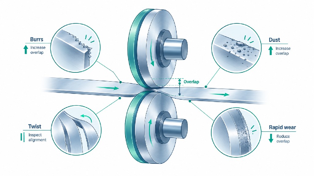
A useful fault guide does not pretend that every defect has one cause. Many visible symptoms can be produced by a worn edge, holder problem, tension instability or inappropriate overlap. The investigation order below prioritizes diagnosis and safe measurement before depth adjustment.
| Observed symptom | Possible overlap-related explanation | Other likely causes to rule out | First verification |
|---|---|---|---|
| Uncut bridges or feathering | Insufficient minimum engagement | Dull blade, low side force, flutter, poor support | Measure real overlap and inspect blade/holder |
| Paper dust rises after increasing depth | Longer bevel contact or changed cut point | Coating abrasion, blade damage, suction fault | Compare trial at prior approved setting |
| Film edge stretches or curls | Excess rubbing near the cut | High tension, temperature, wrong knife type | Inspect cut point and web route |
| Foil shows an intermittent burr | Dynamic knife position varies | Chipped edge, axial runout, lower-ring damage | Inspect both edges and mounted TIR |
| Knife faces show abnormal heat/wear | Excess engagement increases interaction | Excessive side load, poor cant, bearing heat | Verify separate force and cant settings |
| One lane fails while others pass | Local depth or ring position differs | Unequal knife OD, holder wear, spacer problem | Measure each station and actual knife OD |
| Edges deteriorate after regrind | Knife radius changed without correction | Altered bevel, poor surface finish, edge damage | Recheck diameters, geometry and travel |
| Defects emerge only at production speed | Static overlap lacks dynamic margin | Vibration, tension fluctuation, holder play | Compare low-speed and full-speed behavior |
| Unexpected knife jump or edge collision | Insufficient functional engagement under motion | Holder actuation fault, runout, slide damage | Stop, isolate and inspect before restart |
Increasing engagement is the wrong response when the real cause is an incorrectly installed lower ring, bent arbor, damaged bearing or excessive lateral force. It may conceal an intermittent failure for a few hours while dramatically increasing contact and wear. The operator should instead determine whether the problem follows a particular upper knife, lower ring, holder, product roll or speed condition.
A simple fault-isolation record can help. If a defect follows the knife when safely moved to an equivalent approved station, inspect the tool. If it stays with the holder, inspect the holder. If every station fails when a new material lot is introduced, inspect incoming material and web conditions. This logic prevents expensive, repeated knife changes that do not address the process.
Knives are consumable precision components. An edge chipped beyond regrind allowance, a knife below its minimum approved OD, or a blade with uncorrectable runout should not be kept in service simply by finding a more aggressive overlap. A damaged lower ring can similarly compromise a new upper knife. Serviceability must be decided against drawing tolerances, holder limits and inspection results.
See GUANG CHUAN's resharpening versus replacement guide for a broader maintenance decision process. When requesting a regrind, communicate the finished geometry and acceptable OD reduction, not only the desired sharpness. A sharp edge that no longer fits the available overlap window is not a successful repair.
A better tool steel can improve edge retention, but it cannot compensate for a fundamentally incorrect engagement. Likewise, a perfectly adjusted holder cannot make an unsuitable or chipped knife produce consistently clean cuts. The purchasing decision must consider both material properties and the geometry that the knife will maintain over repeated runs.
D2-type cold-work tool steel is often considered for cost-sensitive general industrial knives. M2 and M42 high-speed steels offer different balances of hot hardness, edge performance and cost. Cemented tungsten carbide can improve wear resistance in selected abrasive applications but is more sensitive to impact and chipping, particularly where alignment or holder dynamics are poor. The appropriate grade depends on substrate abrasion, loading, regrind economics and the knife geometry—not hardness alone.
GUANG CHUAN has a dedicated D2 vs M2/M42 HSS vs tungsten carbide slitter knife comparison that addresses this choice in detail. For overlap-focused procurement, the implication is straightforward: request an edge profile and material combination that remains dimensionally consistent through the expected maintenance cycle. A supposedly premium grade that chips whenever the holder vibrates is not a cost-effective upgrade.
| Purchase decision | Why it matters to overlap stability | Evidence worth requesting |
|---|---|---|
| Material and heat treatment | Influences edge retention and damage tolerance | Grade identification, treatment condition and relevant inspections |
| Upper knife OD and usable regrind allowance | Changes geometric engagement after service | Actual new OD, minimum allowed OD and regrind record |
| Bevel and edge finish | Affect bevel contact and material drag | Controlled profile drawing and finish requirement |
| Bore, thickness and seating faces | Influence concentricity and installation repeatability | Drawing tolerances measured from stated datums |
| Lower-ring geometry | Establishes the mating cutting edge | Groove/land drawing, pitch and inspection report |
| Paired-tool consistency | Helps several lanes share equivalent geometry | Matched-set dimensions and identification |
| Holder compatibility | Limits permissible depth and cutting motion | Approved model, gauge and mounting arrangement |
A claim such as “0.005 mm precision” should never stand alone. The buyer needs to know whether it describes radial runout, flatness, thickness variation, parallelism or another feature, at which reference surface and under what inspection condition. Assign tolerances based on the actual machine and final-product specification. Demanding every possible micron-level tolerance can raise cost without improving the cutting result, while omitting one critical location tolerance can make a replacement knife unusable.
The commercial case for precise overlap is not limited to blade life. A stable knife system can reduce wasted web, minimize downstream contamination, make order widths more consistent and reduce the operator time needed after changeovers. However, an equipment or blade supplier should not promise a fixed percentage improvement without a line-specific baseline and a measured trial.
A useful internal cost model separates quality loss, consumables and availability. Quality loss includes rejected rolls, trim waste and material downgraded because of burr or dust. Consumables include knives, lower rings, regrinding, cleaning supplies and labor. Availability includes scheduled knife changes, troubleshooting time and unexpected line stops. Overlap influences several of these categories, but it is not the only driver of any of them.
Consider the following illustrative arithmetic, not a claimed GUANG CHUAN customer result. A line processes material worth $2,000,000 annually and currently loses 1.0% of material value through defects attributable to its slitting process. That is $20,000 of annual material loss. If a validated improvement package—knife geometry, setup control and process changes—reduces the loss rate to 0.7%, the annual avoided material loss is $6,000: $2,000,000 × (0.010 − 0.007). This does not yet account for regrinding, labor, energy, capacity or the cost of the improvement package.
| Illustrative variable | Before | After trial improvement | Calculation |
|---|---|---|---|
| Annual processed material value | $2,000,000 | $2,000,000 | Assumed constant |
| Slitting-related reject rate | 1.0% | 0.7% | Assumed measured result |
| Annual rejected material value | $20,000 | $14,000 | Throughput value × reject rate |
| Annual material-loss reduction | — | $6,000 | Difference before and after |
The purpose of this example is not to imply that changing overlap alone creates a 30% reduction in scrap. A realistic trial may find that most of the improvement came from eliminating runout or changing a blade profile. The commercial benefit still belongs to the validated process change. For purchasing teams, the right comparison is total cost per accepted roll, strip or running hour—not just cost per knife.
A supplier can price a generic disc from a nominal diameter and steel grade. Engineering a reliable replacement pair requires more. GUANG CHUAN's industrial top and bottom slitter knives for paper converting machinery illustrate the relevant product family; its custom industrial blade service supports drawing- and sample-based discussions. A qualified inquiry should identify the exact working system and the failure that the customer wants to avoid.
Include the machine manufacturer, model, holder model, upper and lower knife drawings, actual measured OD/ID/thickness, active bevel, mounting orientation, lower-ring design and installed overlap adjustment range. Add substrate structure, thickness or grammage, running speed, web width, slit count, tension information if known, and the present edge defect. Supply a few well-lit close-up photographs and, where feasible, an inspected sample or the old knife. Remove or obscure confidential customer information as needed.
Ask the supplier to state which dimensional features will be inspected, how replacement knives will be paired with existing anvils, what regrind limits apply, and whether the quotation includes compatible lower rings or spacers. Request a proposed trial and acceptance checklist rather than a broad claim that an alloy is “more durable.” Both parties should agree on the cut-quality metric before discussing any production-performance guarantee.
| Required information | Customer-provided example | Purpose |
|---|---|---|
| Machine and holder | OEM/model/serial or verified drawing reference | Ensures a compatible engagement system |
| Slitting method | Rotary shear, not razor or score | Prevents selection of the wrong tool family |
| Upper knife | OD, bore, thickness, bevel, material, direction | Defines the working edge and mounting |
| Lower knife | OD, profile, groove/land, spacer arrangement | Defines mating geometry and pitch |
| Overlap setup | Target, measured value, adjustment range, datum | Separates actual engagement from dial travel |
| Side relationship | Cant, side force or clearance method | Identifies the other half of the scissor action |
| Product | Material, coating, gauge, width and speed | Establishes the cutting load and failure modes |
| Acceptance | Edge micrographs, dust/burr criteria, width checks | Makes trial results verifiable |
| Maintenance | Regrind count, minimum OD and change interval | Allows total-cost comparison |
| Deliverables | Inspection report, identification, packaging | Supports repeatable installation |
A supplier's catalog may offer standard HSS blades, D2 steel knives and custom carbide options, but purchase specifications should be application-led. If the existing holder cannot accommodate the edge profile or overlap required for a new material, replacing only the blade might not solve the problem. Request an honest assessment of the complete cutting station rather than forcing an incompatible knife into the old mechanical envelope.
For drawings, paired tools or replacement recommendations, send the documented application details through GUANG CHUAN's contact page. The goal is to produce a tooling specification that can be inspected and reproduced, rather than quote an unexplained overlap number.
No. Approximately 1 mm falls within a published DIENES general reference window, but that does not make it universally correct. Valmet provides different values for specific tissue, printing-paper and board applications. The actual range depends on holder design, knife diameters, material and operating conditions. Start with the OEM-approved reference and prove the result at the required production speed.
The phrases are sometimes used interchangeably for rotary web knifeholder settings, but not always. In metal strip processing, penetration before fracture can mean the depth to which the metal plastically deforms or burnishes before its cracks join. That is a material-response quantity. Define the dimension and datum before interpreting any value.
It may force a partial cut to separate temporarily, but it does not restore correct edge geometry. Deeper contact may add dust, heat and wear. Inspect blade sharpness, lower-ring damage, cant, side load and runout first. Replace or regrind tooling that cannot meet the required edge condition within the approved geometry.
The slit may become incomplete or intermittent, especially when dynamic movement or web flutter reduces the effective engagement. In some arrangements the upper blade can climb onto the lower knife, causing severe damage. Stop and correct the cause rather than accepting unstable operation or blindly increasing depth beyond the holder's allowed travel.
Possible results include a longer web travel chord, additional bevel contact, dust, friction, heat, edge deformation, premature wear and an unsuitable cutting-point position. The severity varies with knife profile, web layout, substrate and side-force system. An acceptable edge at slow speed is not sufficient proof of stability at full production speed.
Measure the installed blade diameters and use the machine's approved direct depth gauge, chord gauge or center-distance method. Regrinding changes the outer radius, so an unchanged holder position does not necessarily preserve the original overlap. Confirm the remaining knife diameter is within the OEM's usable limits and that all lanes have compatible geometry.
Not automatically. Film may react differently to friction and deformation, while paper often shows fiber and dust problems. Coatings, thickness, support, tension and holder design all matter. Use the same setting only when a controlled trial demonstrates it meets both products' acceptance criteria with adequate operating stability.
Overlap sets a geometric engagement; side loading maintains the intended lateral relationship between two cutting faces on a contact-loaded holder. Both are important, but they are different adjustments. Changing the regulator pressure may alter contact force without producing the desired change in geometric depth. Follow the holder's specified sequence and measure each correctly.
It is one of several setup dimensions that can influence the shear process, but horizontal clearance, material strength, blade profile, shaft condition and separator setup can be equally or more important. A visible burr does not identify an overlap error by itself. Inspect the edge morphology and use a metal-slitting-specific setting procedure rather than a paper-converting depth chart.
There is no universal value established by the material-test standards cited in this guide. ISO 536 describes paper grammage; ISO 534 addresses applicable paper/board thickness measurements; ASTM D882 addresses thin-plastic tensile testing. These can help define the substrate, but do not prescribe the overlap for every holder. Use applicable equipment manuals, contract specifications and verified trials.
Confirm the knife is sharp and correctly installed, check the web path, side force and cant, and verify the real overlap with the appropriate gauge. If cutting is already complete, test whether excess engagement can be safely reduced within the approved envelope. Compare repeatable dust and edge-quality data at production speed. Cleaning and dust extraction may also require attention.
Not in every case, but the supplier should know the mating geometry. A new upper blade can be damaged by a chipped or incorrectly located lower ring, while a replacement lower knife may change the effective overlap reference. Where a matched set is needed for precision or multiple lanes, request common drawing controls and inspection records for the pairing.
The question “How much slitter knife overlap is needed?” has a practical answer, but not a universal number. For rotary web shear slitting, published sources offer useful reference windows: DIENES discusses approximately 0.76–1.02 mm for many of its applications, while Valmet publishes distinct paper-grade values ranging from less than 0.76 mm for specified tissue applications to about 1.52–2.03 mm for named boards and liner-paper conditions. Those are contextual manufacturer references, not universal requirements for film, foil or metal-coil machines.
The best setting is the one that maintains a complete, stable shear at the intended operating conditions while limiting unnecessary blade-to-material contact. Recheck it after changes to knife OD, bevel geometry, holder mechanics or substrate. Keep vertical engagement separate from horizontal clearance, side load and material penetration at fracture, and document how each number was measured. That is how slitter overlap becomes a repeatable engineering control rather than a depth adjustment based on guesswork.
Need replacement rotary shear knives or help defining a paired upper/lower blade specification? Review GUANG CHUAN's circular slitter knife selection guide and precision slitting knife products, then send your drawings and process requirements for an application-based quotation. Clear dimensions, an explicit overlap datum and agreed test criteria help make the purchase more reliable—and the slit edge easier to control.

Leave A Message
Scan to WhatsApp :

 English