




Practical rotary shear-slitting guidance for converting engineers, maintenance teams and industrial knife buyers.
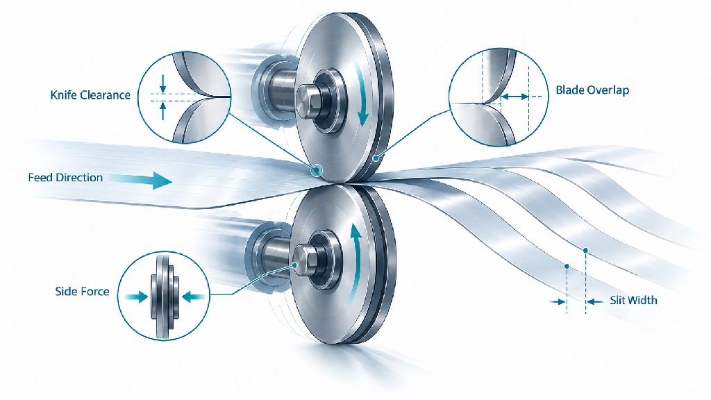
A circular slitter knife can be made from premium tool steel, ground to a sharp edge and installed on an expensive rewinder—and still produce fuzzy paper edges, stretched film, foil burrs or premature knife wear. In many cases the cause is not simply blade quality. It is the relationship between the upper knife, lower knife or anvil ring, holder, moving web and machine geometry. Three adjustments deserve particular attention: slitter knife clearance, blade overlap and side force.
These terms appear on machine drawings, operator screens and purchase orders, but they are not always defined consistently. “Clearance” might mean a gap before the upper knife engages, a lateral gap between two shear faces, or the installed spacing of a stacked rotary shear system. “Overlap” might be displayed as depth, penetration or an electronic knifeholder setting. “Side force” might be entered as an air pressure even though actual force depends on the holder mechanism. Without a shared vocabulary, technicians can follow apparently correct instructions and obtain different cuts.
This guide explains those differences, offers a repeatable slitter setup procedure and shows what should change when converting paper, polymer film, aluminum foil or a laminate. It also demonstrates how to evaluate knife specifications, diagnose edge defects and communicate with a replacement-blade supplier. The aim is not to prescribe one magic number; it is to make adjustments measurable and purchasing decisions defensible.
Important scope and safety note: This article primarily concerns rotary shear slitting with an upper circular knife against a lower knife, band or anvil ring. Razor and score slitting use different contact mechanics. Numerical settings quoted from individual manufacturers apply to their specific equipment, not to every slitter. Stop the equipment, isolate hazardous energy and follow the original equipment manufacturer's (OEM's) procedures before inspecting or adjusting any blade.
Slitting quality is often judged by the appearance of a single sample, but a commercial converting line must maintain edge quality over an entire production order. A roll with a few ragged sections can create customer complaints downstream. Paper dust may contaminate print equipment; film edge stretch can generate wrinkles and poor registration; a foil burr may damage a laminate or violate a customer’s edge acceptance standard. A single bad slit can also upset winding tension across neighboring lanes.
A stable slitting process must achieve four things simultaneously. It should separate the web cleanly, keep the resulting lanes close to their specified widths, avoid damaging or contaminating the material, and run for a commercially useful interval before maintenance. More aggressive blade contact may temporarily improve cutting, yet increase friction, heat, edge chipping and bearing loads. A very light contact may protect a sharp knife while allowing intermittent uncut fibers or film tails. Effective setup is a controlled compromise among these outcomes.
A useful mental model is to treat the cutting system as a chain of tolerances and forces. Web properties determine the cutting load. Knife geometry supplies the cutting edge. The holder positions and loads it. The arbor and lower knife define the mating surface. Winder tension and web path determine how material enters and leaves the cut. If one link changes, the correct setting for another link may change too.
For additional context on knife families and materials, see GUANG CHUAN's existing Circular Slitter Knives: Types, Applications, Materials and Selection Guide. That overview explains the selection problem; the present article focuses on the operating geometry needed to make those knives perform.
An acceptable production trial should produce clean edges on both sides of a slit, not merely one visually attractive strip. The knife should run without abnormal vibration or rising temperature, and the result should remain stable as line speed and roll diameter change within the approved operating window. The technician should be able to reproduce the setup after the blade has been cleaned, replaced or reground. These requirements should appear in a commissioning or supplier acceptance plan rather than remaining informal operator knowledge.
Imagine an upper disk with a sharpened perimeter descending beside a hardened lower ring. The two edges pass closely enough to initiate a shear zone in the moving material. In a controlled shear cut, the web does not simply break because the upper knife presses it downward; cutting develops through the local interaction of edge geometry, lateral alignment, material deformation and relative movement. The lower ring is therefore a precision cutting component, not just an ordinary support roller.
The top knife may rotate from web traction, from contact with a driven lower knife, or through a dedicated drive, depending on the equipment. A lower anvil may be driven at a defined speed. The correct arrangement is specified by the machine manufacturer, including web approach angle, wrap or tangent geometry, knife orientation, direction of rotation and the permissible relationship between anvil surface speed and web speed.
A shear-slitting holder commonly performs a sequence of motions: it approaches the lower ring, establishes the required geometric overlap and then applies lateral loading to maintain controlled contact. Valmet describes a comparable approach-and-side-load sequence in its winder slitter adjustment guidance. Not every holder follows the same sequence; mechanical and pneumatic systems may use different linkages.
This is why a good setup drawing should show at least two views. The front view establishes vertical overlap between the knife and ring; the side or plan view establishes the lateral relationship, contact face and cant angle. A single close-up photograph does not normally reveal all of these dimensions. If a supplier offers only the blade outside diameter and bore, important information about mating geometry remains missing.
Razor slitting uses a very sharp thin edge to penetrate a film or web, either in air or against a suitable support. Score slitting presses a blade into material against a hardened backing surface. Rotary shear slitting works with two cooperating shearing edges. Each method can be appropriate, but an operator should not transfer a shear knife’s overlap or side-force setting into a razor or score system. The first engineering decision is to identify the actual slitting method and confirm the machine’s intended operating mode.
Slitter knife clearance is often the least precise term in a workshop conversation. On some shear-slitting holders, the “blade-to-band gap” means the horizontal separation before lateral engagement, when the blade has been unloaded or retracted from the band. That is a setup dimension of the holder mechanism. Valmet, for example, specifies a 4–6 mm (0.16–0.24 in.) unloaded band/blade gap for the particular Valmet slitter positioning arrangement described in its service article. It is not a universal working clearance between the two cutting edges.
In a different machine, particularly a fixed arbor arrangement, “side clearance” can mean the designed separation between adjacent cutting faces while they shear. In a spring-loaded upper-knife system, the cutting faces may instead run in controlled contact, so the effective cutting relationship is established by side force, face geometry and holder deflection—not by leaving an arbitrary 4 mm gap. A literal transfer of the Valmet pre-engagement dimension to the engaged cutting zone would cause a serious misunderstanding.
For every maintenance record or purchase drawing, state whether the measurement is pre-engagement blade-to-band gap, engaged lateral face relationship, spacer-controlled axial separation, or another machine-specific dimension. Record the measurement location, reference face, operating state, measuring tool and unit. Avoid writing “clearance = 0” without explaining whether contact is intended and how it is controlled.
Blade overlap is how far the upper and lower knife outlines pass one another in the radial or depth direction when they are engaged. It is also called penetration or engagement depth. On a suitable geometrical diagram, it can be expressed as the sum of the two effective radii minus the distance between their centers along the applicable geometry; the machine’s own measuring convention controls how this is verified. Tidland's Control Series Class I knifeholder manual instructs users to measure overlap on the common centerline, or from the chord formed where the knife outlines intersect.
Too little overlap can allow an upper knife to ride onto the lower ring or fail to finish separating the web. Too much can promote edge damage, heat, abnormal contact and premature dulling. Crucially, overlap is not a thickness setting: a 25-micrometer film is not automatically slit with 25 micrometers of overlap. The overlap must suit the knife diameter, holder, lower ring, web path, grade, speed and cutting method.
Side force, also described as lateral load or side loading, pushes the upper knife toward the mating face of the bottom knife. It supports a stable shearing relationship. The objective is generally the minimum side force that maintains an acceptable cut under real production conditions, not the maximum force the holder can deliver. Excess force increases friction and blade wear, while insufficient force can allow cutting faces to separate during load fluctuations.
Side force must not be confused with down force. A pneumatic regulator shows pressure; the delivered lateral force also depends on effective cylinder area, friction, lever geometry and spring characteristics. As a first-order physical relationship, force equals pressure times effective area, but an actual knifeholder requires the OEM’s calibration or a correctly performed force-gauge procedure. Do not compare two machines simply because their regulators display the same pressure.
| Term in a setup sheet | What it should mean | Typical source of confusion | Better record entry |
|---|---|---|---|
| Clearance or gap | Precisely identified lateral separation or contact state | Confusing unloaded holder gap with cutting clearance | “Blade/band unloaded gap, measured at OEM reference: ___ mm” |
| Overlap or depth | Radial engagement of upper and lower cutting outlines | Mistaking web thickness or knife protrusion for overlap | “Engaged overlap, measured per OEM method: ___ mm” |
| Side force | Lateral force holding shearing faces in their intended relationship | Treating regulator pressure as direct force | “Measured force: ___ N; regulator: ___ bar; tool/method: ___” |
| Cant angle | Small directional angular relationship of knife and anvil faces | Assuming one angle suits every holder | “Installed OEM cant key/angle: ___” |
| Runout | Radial or axial variation under rotation | Quoting blade-only tolerance while neglecting arbor | “Assembly radial/axial TIR at stated points: ___ mm” |
There is no responsible universal clearance-overlap-side-force chart covering tissue, coated board, PET film, laminated packaging and battery foil. The following figures are valuable because they come from actual equipment documentation. They also reveal how differently two legitimate slitting systems can be designed.
In its published guidance on slitter adjustments, Valmet provides the following example ranges for specified winder equipment and paper grades. The force values refer to that arrangement and should not be copied into an unrelated knifeholder. The overlap values have been converted from inches for convenience; rounding does not improve original measurement precision.
| Paper grade | Manufacturer-side-force guidance | Manufacturer overlap guidance | Appropriate interpretation |
|---|---|---|---|
| Tissue paper | 12.8–15.1 lbf (about 57–67 N) | Less than 0.030 in. (less than 0.76 mm) | Model-specific, light-paper reference |
| Printing paper | 15.1–17.3 lbf (about 67–77 N) | About 0.030–0.050 in. (0.76–1.27 mm) | Model-specific paper-winder reference |
| Light or coated board | 17.3–21.8 lbf (about 77–97 N) | About 0.050–0.060 in. (1.27–1.52 mm) | Model-specific board reference |
| Linerboard | 19.1–23.2 lbf (about 85–103 N) | About 0.060–0.080 in. (1.52–2.03 mm) | Model-specific heavier-grade reference |
Valmet additionally describes a 4–6 mm unloaded blade/band gap for its described positioning system. That figure is intentionally kept out of the overlap column because it describes a different measurement. The ranges above illustrate the manufacturer’s response to heavier paper grades; they should never be presented as a specification for thin film or foil.
The Tidland / Maxcess Control Series Class I installation and maintenance manual gives a factory-configured default overlap of 0.035 in. (0.889 mm) and side force of 2 lbf (approximately 8.9 N). Its specification table lists overlap positioning accuracy of ±0.013 mm, blade diameter 90 mm, maximum specified side force 26.7 N (6 lbf) and a rated design maximum of 1,000 m/min. These figures characterize a named electronic knifeholder, not all circular slitter knives, and the maximum speed is a holder design rating—not a guarantee that any material can be slit successfully at that speed.
The different force levels between the Valmet paper-winder example and the Tidland holder immediately show why copying values from an online chart is unsafe. Mechanical architecture and measurement conventions differ. The Tidland troubleshooting guidance explicitly connects excessive side force and overlap with damaged edges and short blade life. It also warns that combining maximum side force with minimum overlap can cause the blade to climb onto the anvil. The correct commercial message is control the relationship among settings, not “increase every setting until the cut improves.”
Engineering rule: Start from the exact machine and knifeholder manual. Treat third-party published figures as evidence of possible design ranges, never as authorization to exceed OEM limits. For a new product grade, validate changes through guarded trial runs and documented edge-quality checks.
A paper web, a biaxially oriented polymer film and an aluminum foil are not interchangeable cutting loads. Basis weight, thickness, tensile properties, coating, brittleness, elasticity, adhesive tack and direction of processing affect how each reacts at the blade. Two webs having the same thickness may require different cutting geometry because their deformation and fracture behavior differ.
A useful incoming-material specification therefore combines dimensions with functional information. For paper, grammage and caliper are different properties: ISO 536:2019 defines a method for measuring paper and board grammage, while ISO 534:2011 addresses thickness, density and specific volume. These standards support consistent material characterization, but neither publishes a universal slitter knife clearance. Consult the respective ISO 536 description and ISO 534 description.
For thin polymer film, ASTM D882 provides a standardized method for tensile-property testing. Its relevance is that film behavior changes with specimen dimensions and testing conditions; it does not supply a rotary shear knife setpoint. The current ASTM D882 specification is useful when buyers compare material batches or discuss web-handling requirements. For flexible packaging aluminum foil, ASTM B479-19 covers specific annealed aluminum and aluminum-alloy foils, including material as thin as 0.0064 mm and below 0.15 mm. These are material-scope figures, not recommended overlap or clearance values.
| Substrate family | Main slitting concern | Variables to collect before adjustment | What to validate on finished slit |
|---|---|---|---|
| Tissue and lightweight paper | Fiber pull, feathered edges, dust | Grammage, caliper, moisture, fiber direction, speed | Fiber integrity, lint count, clean winding |
| Printing and coated paper | Dust, coating fracture, edge roughness | Coating type, basis weight, surface finish, tension | Coating continuity and slit-width stability |
| Paperboard and liner | High cutting load, edge crush, knife wear | Thickness, stiffness, caliper variation, grade | Square edges, minimal crushing, stable load |
| BOPP, PET and other films | Edge stretch, tails, wrinkles, heat | Film thickness, orientation, tensile response, temperature | Flat edges, no necking, low particles |
| Adhesive-coated webs | Adhesive build-up, edge smearing | Tack, coating weight, liner, cleaning interval | Clean release and consistent adhesive edge |
| Aluminum or copper foil | Micro-burrs, particles, folding, tearing | Alloy/temper, actual gauge, surface finish, tension | No unacceptable burrs, particles or cracks |
| Paper/film/foil laminate | Layer separation and mixed fracture | Layer sequence, bond strength, total caliper | No delamination, clean multilayer edge |
The table indicates what to investigate; it is deliberately not a chart of automatic numerical setpoints. A converter should select a baseline from its machine manual, test the actual material and record the narrow operating window that satisfies its customer’s acceptance criteria.
Paper looks comparatively easy to cut until a line runs continuously at commercial speed. Low-basis-weight paper can shed fibers if the shear is incomplete. Coated paper can generate dust or fractured pigment at the slit. Heavy board can push the upper knife sideways, increase required support force and damage edges if the cutting geometry is unstable. Humidity, incoming roll profile and web tension further complicate repeatability.
Start by recording paper grade, grammage, caliper, moisture or conditioning condition, target slit width and web speed. Examine a freshly cut edge with a consistent inspection method rather than relying only on the naked eye. Look at both the retained lane and the trim strip. If fiber pull occurs only on one side, suspect knife orientation, lower-ring condition or asymmetric contact before blaming the paper batch.
When an approved paper-grade recipe exists, restore the recorded overlap and measured force before experimenting. If an incomplete cut or fiber bridge persists, inspect edge sharpness and radial position first. Increasing overlap may help an insufficiently engaged knife, but excessive overlap can bend or fold the web. If the cutting faces intermittently separate, adjust lateral support cautiously within the OEM limit. If dust increases as force rises, revert to the last verified setting and look for edge wear, incorrect cant or lower-ring runout.
A critical operational distinction is between short-term edge appearance and long-term production stability. An extra force increment might produce an initially crisp edge while increasing wear enough to create more dust later in the shift. After each adjustment, check the first meters and a representative length at steady-state speed. Log the number of roll changes or running distance before the cut deteriorates, not just the time at the start of the order.
For common paper converting applications, GUANG CHUAN supplies top and bottom slitter knives for paper converting machinery. A paired-knife assessment is particularly useful when a customer reports repeated upper-blade replacement with little improvement, because the mating band may be damaged or out of specification.
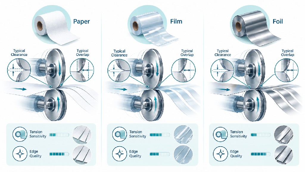
Film often rewards a lighter cutting interaction than heavier paperboard, but it is less tolerant of tension disturbance and edge deformation. Thin PET, BOPP, PE and specialty films can stretch around a blade before separating, especially where the edge is rounded, the support is unstable or the web is poorly presented to the cutting zone. A visibly narrow “necked” region, string-like tail or periodic wave may indicate a mechanical cutting problem rather than a bad film formulation.
Begin with a trial configuration appropriate to the specific film and slitter design. Check orientation of single-bevel edges, the lower-knife condition, the expected web path and contact geometry. On thin optical or electrical film, small particles may be more important than a cosmetically imperfect edge. Inspect under magnification where the product specification requires it. Measure the slit width after the film has relaxed under controlled conditions; an unstable web tension can make a blade look inaccurate even when its machined dimensions are correct.
If a line shows excessive edge stretch, do not automatically increase side force. First verify that the knife is sharp, the cant arrangement is correct and the material is not being dragged over an inappropriate contact face. Check web tension, upstream guiding, static control and winding settings. Overlap and side force should be adjusted one at a time and only within the approved range. An adhesive layer may additionally require a cleaning and anti-build-up strategy; increasing blade load does not solve a sticky coating accumulating on the face.
Some high-value films may perform better with a different cutting method, including a specialized razor or an optimized shear system. Changing methods requires a full evaluation of particles, edge deformation, web support, tool life and machine compatibility. The goal is not to prove that shear cutting is always superior; it is to select a method with repeatable, documented outcomes for the specific product.
For tape and converted film operations, GUANG CHUAN also offers 250 mm circular slitting blades for BOPP and masking-tape rolls. Blade dimensions must still be checked against the intended machine; a matching outside diameter alone is not sufficient evidence of compatibility.
Thin metal foil is particularly sensitive to an unsuitable combination of cutting-edge sharpness, support, alignment and tension. Unlike a polymer film, metallic foil may exhibit tiny burrs or local work deformation near the shear edge. Excess overlap or side loading can increase rubbing and damage, while insufficient engagement may leave uncut zones or irregular fracture. The result depends on alloy, temper, foil thickness, coating, web width and machine design.
Avoid using an everyday rule such as “set the blade clearance to ten percent of material thickness” for all rotary foil slitters. Clearance percentages sometimes discussed for conventional sheet-metal shearing or other cutting equipment do not automatically transfer to spring-loaded circular shear knives processing micrometer-scale foil. The mechanism, support geometry and acceptable burr-height limit are different. A specification must distinguish whether the system uses controlled face contact, fixed side clearance or another arrangement.
For flexible packaging aluminum foil, ASTM B479-19 is a useful procurement reference for alloy and thickness coverage; it should not be represented as a blade-setting standard. Battery-related foils may have very different cleanliness, dimensional and particle requirements, which must come from the actual customer or process specification. Never promise a “zero-burr” result solely from a nominal hardness or tolerance figure.
A practical foil trial should combine microscopy of both edges, particle collection where relevant, controlled slit-width measurement, and an inspection of downstream winding or lamination behavior. Look for periodic edge defects that repeat with one knife revolution: these can point toward chipped edges, eccentricity or local lower-ring damage. A continuous burr on one side may suggest incorrect blade orientation, engagement or side relationship. Confirm the defect mechanism before ordering a harder knife material.
GUANG CHUAN describes multi-groove, multi-edge bottom slitter rotary blades for metal foil, paper and composite materials. Where multiple grooves are used, groove pitch, land form and alignment with the upper cutters require particular care because one out-of-position lane can affect an entire multi-strip order.
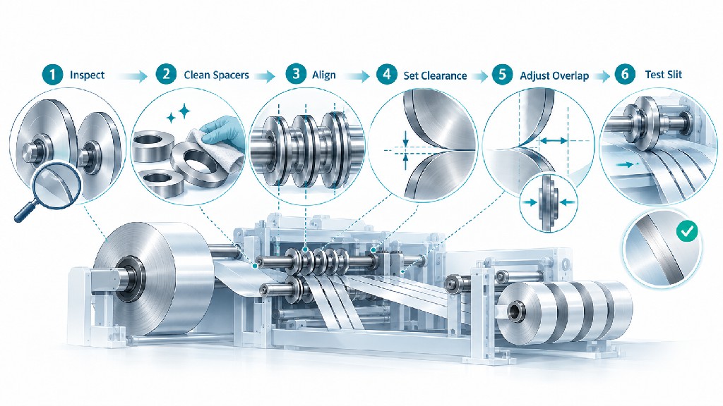
The purpose of a documented setup is to replace trial-and-error changes with a controlled sequence. The sequence below is an engineering workflow, not a substitute for the specific OEM operation, isolation and maintenance instructions. It must be adapted to the machine's guarding, automatic movement, energy sources and authorized maintenance roles. In the United States, OSHA 29 CFR 1910.147 defines requirements for controlling hazardous energy during applicable servicing and maintenance. Other jurisdictions have their own requirements.
Record the web material, nominal and measured thickness or grammage, coating and adhesive details, target lane widths, original roll width, production speed, web tension settings, and the current knife assembly part numbers. Identify the knifeholder and lower-ring model, its operating manual revision and whether the cut is shear, score or razor. If there is a proven recipe for this exact combination, use it as a baseline.
Photograph the machine's current settings, but never rely on a photograph as the only record. Capture numbers, units, holder position, direction of rotation and whether the values are commanded setpoints or actual measured readings. If the machine has several slit positions, record each station separately; one worn holder or misaligned lower ring may create a defect on only one lane.
Stop web motion and wait for complete cessation of rotation. Follow the machine-specific lockout/tagout and verification procedure covering electrical power, pneumatic or hydraulic pressure, stored spring energy, gravitational motion and any automatic knifeholder actuation. Use the authorized maintenance method and appropriate blade-handling equipment. A stopped spindle can still be dangerous if a cylinder unexpectedly engages. Never place fingers between shearing edges to judge contact or sharpness.
Valmet's safety instructions specifically caution against touching sharp edges, attempting to stop rotating knives by hand, catching falling blades or reusing damaged blades. Use purpose-made gauges and guards. Where an OEM requires a particular loaded measurement state, only trained and authorized personnel should establish that state under the approved safety procedure.
Check the upper knife and lower ring for chips, flat spots, scoring, pitting, corrosion and adhesive build-up. Examine the machined mating faces, not only the cutting tips. Confirm that the knife sits cleanly against its shoulder or hub, and that the clamping elements are undamaged and correctly installed. Check the lower anvil for runout and inspect the guide bar, bearings, cartridge and slide for looseness.
Do not assume a newly purchased blade is immune to installation problems. Dirt trapped between a blade face and a hub may create axial wobble. A worn spindle bearing may produce periodic lateral movement that cannot be corrected by grinding a better knife. If a knife has been reground, confirm its new outside diameter, edge profile and the holder's remaining adjustment and guard compatibility.
Use the manufacturer-defined measurement for the particular holder. For equipment that specifies a pre-engagement blade/band gap, measure it in the specified unloaded position, at the indicated reference point. For a fixed-arbor system, verify knife and spacer thicknesses and face locations against the stack drawing. For a controlled-contact upper knife, verify that its side-stroke travel and geometry allow intended contact without bottoming out or mechanical interference.
Inspect every lane after a width change. Moving a knifeholder or lower-ring assembly independently may alter its clearance, preload or contact alignment. A machine with electronic positioning can still require mechanical verification after service, collisions or component replacement.
Establish blade overlap only by the OEM procedure and tool. Where permitted, use a chord gauge, controlled measuring instrument or calibrated electronic setting. Confirm that the resulting engagement is consistent with the blade's actual reground diameter, not merely the original catalog diameter. Verify correct guard coverage and that the knife does not hit the wrong lower-ring surface.
The geometric reason matters. For a simple two-circle engagement, reducing an upper knife from 90 mm to 88 mm outer diameter reduces its radius by 1 mm. If the center positions are unchanged, the nominal radial overlap is also reduced by 1 mm. The example is pure geometry, not a recommended regrind allowance. Actual knifeholders may compensate automatically or use a different mechanical reference, so verify the result rather than calculating once and assuming it is correct.
Restore the OEM baseline. If adjustment is authorized, increase contact only as required for reliable cutting, while watching for worsening edge damage or evidence of rubbing. Some machines allow a direct side-force setpoint; others use a regulator that changes pneumatic pressure. A proper force measurement must follow the holder manufacturer's method. Valmet describes use of a force gauge to determine the force needed to move its blade away from the band. That method must not be improvised on a rotating knife.
Keep the overlap fixed when evaluating the effect of side force. Otherwise it becomes impossible to tell which variable improved or damaged the cut. Do not defeat hard stops, force limits or holder calibrations to extend the available range.
Cant angle describes a deliberate angular relationship that can help maintain appropriate cutting contact. It is usually designed into a particular holder, key or mounting configuration. One manufacturer's angle cannot be transferred to another manufacturer's assembly. Verify blade orientation relative to web travel and any installed cant key. Examine the lower anvil, drive, web guide, tension system and winding layout for problems that could be mistaken for cutting defects.
Where a driven anvil is used, consult its required speed relationship. For example, Tidland's Class I manual discusses a 3–5% driven-anvil overspeed as a troubleshooting measure for its applicable system. That is not blanket permission to run every foil or film anvil faster than the web. Such speed relationships should be treated as design-specific instructions, especially when delicate webs are processed.
After the machine has been returned to its guarded, safe operating condition by authorized personnel, run a trial using the approved start-up process. Inspect the first material at reduced speed, then at the intended operating speed if permitted. Record the same outputs each time: edge appearance, particles or dust, slit width, winding quality, web breaks, knifeholder behavior and time to edge deterioration. Compare results against a defined customer acceptance standard.
Change only one setup variable per trial. If an issue remains after reasonable OEM-permitted adjustment, stop and investigate the physical condition of the tool, lower ring, holder or web. Once a stable result is found, save the approved settings and the test conditions together. A recipe without the associated material, blade dimensions and acceptance criteria is not a repeatable manufacturing instruction.
Operators frequently discover that their measurement tools are more important than their initial adjustment intuition. A dial indicator can reveal runout; it cannot directly prove that a cut is clean. A force gauge can help characterize lateral load; it cannot replace inspection of the mating faces. A microscope can reveal an edge burr; it cannot by itself identify whether the cause is side force, poor sharpening or anvil eccentricity.
| Tool or method | Appropriate inspection | Limitation to remember |
|---|---|---|
| OEM overlap or chord gauge | Engaged radial relationship | Must match holder geometry and gauge procedure |
| Dial indicator with rigid fixture | Radial or axial total indicated runout (TIR) | Reads the assembled system and mounting influence |
| Outside micrometer or calibrated gauge | Blade thickness, spacer dimensions, diameters | Use suitable contact pressure on fine edges |
| Force gauge | Lateral loading under OEM procedure | Do not measure on rotating or unexpectedly energized assemblies |
| Optical comparator or tool microscope | Edge profile, bevel, chips, burrs | Lighting and orientation affect perceived defects |
| Calibrated slit-width measurement | Finished strip width and repeatability | Material tension and relaxation can affect readings |
| Portable inspection light and magnification | Paper fibers, film tails, foil burr patterns | Establish a consistent acceptance criterion |
| Temperature or vibration monitoring | Emerging bearing or friction problem | Changes are diagnostic signals, not blade tolerances |
A measurement plan should include the condition in which values are recorded. “Axial runout 0.01 mm” is ambiguous without specifying whether it is on a loose blade, a clamped assembly or an operating shaft; where the indicator contacts the part; and whether the result is TIR. For precision slitters, these distinctions can decide whether a seemingly good replacement knife performs correctly after installation.
Even a nominally excellent blade cannot cancel errors accumulated in an arbor, mounting shoulder, spacer stack and bearing. As a practical matter, inspect the assembled cutting system when troubleshooting repeated defects, especially if different blade suppliers appear to produce the same symptoms.
Three variables may be adjustable at the machine, but several crucial variables are manufactured into the knife. These include outside diameter, inner bore, thickness, bevel angle, edge radius, face flatness, parallelism, concentricity, heat treatment, surface finish and grinding direction. Choosing a stronger alloy without controlling these features can produce a knife that lasts no longer than the previous one.
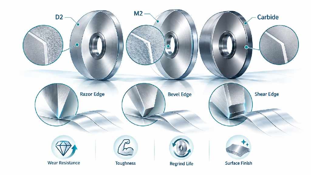
Bevel geometry. A single-bevel upper knife has a defined working orientation. Reversing it may move the effective cutting edge away from the intended lower-ring contact face. A double-bevel blade may be suitable in another system, but the drawings must show where the functional edge lies. Hollow grinding, relief surfaces and compound profiles should be specified by the actual equipment requirements—not by the photograph of a similar blade.
Bore and mounting. A blade that fits over a shaft with excessive clearance can shift under side load. An incorrect keyway or locating-hole pattern can create eccentricity or incomplete face support. Clamp torque and mounting cleanliness are just as important as nominal fit. For a precision assembly, provide all relevant datum surfaces in the drawing and request the supplier's inspection reference.
Material and heat treatment. D2/SKD11-type tool steels, M2-type high-speed steels and tungsten-carbide grades are among possible choices for industrial slitting, each with different balances of toughness, abrasive wear resistance and edge behavior. The suitable choice depends on the cut material and the actual grinding profile. Greater hardness may improve abrasion resistance in one application while increasing chipping risk in another. Ask for a justified material recommendation rather than buying the hardest nominal grade.
Regrinding. Regrinding can restore an edge, but every operation may change outside diameter, bevel width, geometry or available overlap adjustment. Establish a permitted regrind profile and minimum usable diameter from the holder manufacturer. Tidland's published minimum diameter for a named 90 mm Class I configuration is a model-specific limit, not a universal service rule for a 90 mm circular blade.
GUANG CHUAN's custom industrial blade services describe production from drawings or physical samples, selection among tool steels and carbides, and precision grinding. When specifying a replacement set, request the dimensional features, mating orientation and inspection records required to establish repeatable cutting quality, rather than relying on material grade alone.
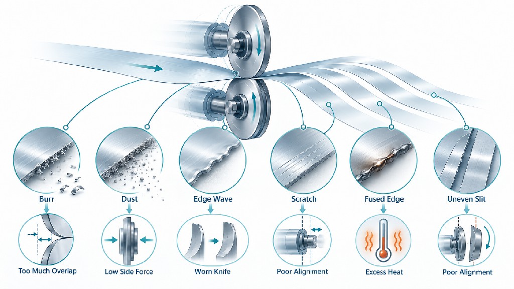
Random changes to clearance, overlap and force can hide the true cause while damaging expensive knives. A structured troubleshooting table begins with the observed defect, identifies plausible sources and suggests a safe verification order. The symptoms below are diagnostic possibilities rather than guaranteed one-to-one causes; a real failure may involve several interacting variables.
| Observed defect | Possible slitter-related causes | First checks before changing the recipe |
|---|---|---|
| Fuzzy paper edge or fiber bridges | Dull edge, insufficient effective shearing, wrong cant, excessive overlap | Blade condition, anvil face, cant, holder alignment |
| Heavy paper dust | Edge damage, excessive rubbing, coating fracture, unstable overlap | Both cutting faces, runout, material/coating batch |
| Film tails or uncut threads | Edge wear, unstable side contact, wrong method for substrate | Sharpening, contact behavior, web support |
| Film edge stretch or curl | Too much local deformation, web tension, poor geometry | Tension, blade orientation, overlap, web path |
| Foil micro-burrs | Chipped knife, incorrect engagement, lower-ring damage | Microscope, mating face, runout and orientation |
| Foil wrinkling or tearing | Tension, local drag, poor slit separation | Web handling first; then contact settings |
| Premature knife wear | Excessive side force or overlap, debris, anvil runout | Measured force, depth, mating condition |
| Repeating defect at knife pitch | Eccentricity, local edge chip, spindle or anvil problem | Assembly runout and circumferential inspection |
| Unstable slit width | Web guiding, tension variation, lateral shaft/holder movement | Guiding, lane measurement, bearings and mounting |
| Upper knife climbs onto lower ring | Unstable combination of overlap and side load | Stop; check OEM guidance and possible edge damage |
The Tidland knifeholder troubleshooting section is especially instructive: fuzzy edges may relate to worn or wrong cant components, loose mounting and too much overlap, while short blade life may relate to force, overlap or anvil runout. It also warns against the particular combination of high side force and minimum overlap. These examples demonstrate why each defect should trigger a sequence of checks, not a single automatic knob adjustment.
First, determine whether the problem is isolated to one station or visible across all lanes. A single-lane defect often points to its knife pair, lower ring, holder or local mounting. A simultaneous defect across every lane suggests material, web handling or common-machine changes deserve attention. Second, determine whether the problem appeared suddenly, gradually or after maintenance. Sudden failure may indicate damage or installation error; gradual degradation may indicate wear or contamination.
Third, check whether the symptom changes with speed or tension without moving the knifeholder. A speed-dependent problem can expose vibration, runout, web flutter or differential contact. Finally, compare the suspect blade and holder with a known-good station where an approved, safe exchange test is possible. Maintain traceability so the team can distinguish whether the fault follows the blade, holder or machine position.
Production teams often focus on maximum web speed because it appears directly on a machine specification. However, maximum speed is meaningful only when the slitting geometry, material handling and rewind quality can sustain acceptable output. A cut that fails after twenty minutes at a nominal 1,000 m/min may be less productive than one that stays stable for hours at a lower qualified speed. The appropriate operating speed is determined by the entire process, not the blade material alone.
For a rotating circular component, the ideal geometric relation between peripheral speed and rotation rate is:
Peripheral speed (m/min) = π × outside diameter (m) × revolutions per minute (rpm).
As a purely mathematical example, a 100 mm diameter circle operating at a peripheral speed of 600 m/min corresponds to approximately 1,910 rpm. Actual knife rpm depends on the drive, slip, contact conditions and the system's designed speed relationship. Do not set rotational speed from this equation alone. The example is useful for checking whether a proposed tool, bearing or drive has been specified at an appropriate operating speed.
Diameter loss also affects setup after grinding. If two otherwise identical upper knives differ in outside diameter, they may no longer have the same effective overlap at a fixed center position. Differences become more important when many stations are expected to produce identical cuts. Mixed regrind states should therefore be documented and verified, particularly on multi-lane production lines.
A procurement specification should request both permissible blade dimensions and relevant operating conditions. “Suitable for 600 m/min” is incomplete without substrate, contact design, edge-quality target and expected maintenance interval.
Good process optimization is an experiment with a written result, not a list of settings someone remembers using years earlier. Once the machine is safe and mechanically sound, define the baseline from the OEM and a known acceptable product. Select a measurable output such as dust mass per inspection interval, width variance, visible defect count, web-break rate or the distance between sharpening interventions.
A small test matrix can help separate the effects of overlap and side force, provided every tested value is within the OEM's approved operating envelope. For example, compare a baseline overlap with a modestly changed overlap while holding force constant; then return to the best verified overlap and evaluate an approved change in force. Replicate the best condition rather than assuming that one favorable sample proves long-term stability.
| Trial | Overlap condition | Side-force condition | Observations to record |
|---|---|---|---|
| A: reference | OEM-approved baseline | OEM-approved baseline | Edge quality, width, particles, run stability |
| B: overlap study | One OEM-permitted adjustment | Same measured force as A | Which defects improve or worsen? |
| C: force study | Return to selected overlap | One OEM-permitted force adjustment | Is the cut stable without extra wear? |
| D: confirmation | Best safe combination from prior trials | Best safe combination | Repeat after steady running and restart |
The table deliberately contains no universal 0.1 mm increment or pneumatic-pressure step. Such values can be too large for one holder or too small to measure repeatably on another. Specify an adjustment increment from the OEM's control resolution, mechanical capability and process risk. On delicate film and foil, the acceptance plan should include contamination, edge damage and downstream performance, not only whether the web physically separates.
Maintain a controlled recipe record including machine model, knifeholder, upper and lower knife identification, actual diameters, material lot, ambient or material condition where relevant, approved overlap, measured side force, production speed, tension, inspection method and operator authorization. That record becomes evidence for future troubleshooting and for new blade-supplier qualification.
Knife cost matters, but the procurement objective is the lowest sustainable cost per acceptable unit of production. A lower-priced knife that creates dust, reduces speed or requires frequent stoppages may be more expensive in service. Conversely, a premium alloy is not automatically economical if a misaligned holder destroys its edge in the same time as a standard knife.
Consider an illustrative calculation, not a reported GUANG CHUAN customer result. Suppose a slitting line has an average web width of 1.2 m, operates at 300 m/min for 8 scheduled hours and achieves 85% running availability. The approximate web area processed is 1.2 × 300 × 60 × 8 × 0.85 = 146,880 m². If reject and trim-related loss attributable to the process improves from 3.0% to 2.0% of this processed area, the difference is 1,468.8 m² of potentially recovered material per shift. Its monetary value depends on actual material cost, customer requirements and whether the loss is recoverable or saleable.
The same illustration shows why measuring yield matters. If a production report records only knife purchases, it ignores recovered web, prevented roll rejection and uptime. A more complete cost model includes blade purchase and sharpening, labor for changeovers, planned and unplanned downtime, discarded material, cleaning, maintenance of bearings and holders, and the economic cost of delayed shipments.
| Cost category | Metric a buyer can actually track | How slitting quality affects it |
|---|---|---|
| Knife purchases | Cost per matched knife set | Edge life and material choice |
| Sharpening | Cost and number of safe regrinds | Grindable geometry and wear pattern |
| Changeover labor | Minutes per knife change | Holder accessibility and repeatable installation |
| Downtime | Unscheduled minutes per production order | Breaks, poor edge quality and cleaning |
| Material loss | Rejected m², kg or rolls | Burrs, dust, wrinkles and incorrect widths |
| Customer quality | Rejections, credits or complaints | Slit acceptance and downstream performance |
| Output capacity | Accepted rolls or square meters per shift | Qualified speed multiplied by actual availability |
For a purchase decision, ask a prospective supplier for a paired-tool quotation, dimensional inspection data, a documented regrind plan and a trial-evaluation proposal. Those details make a quote comparable in engineering terms, rather than forcing the buyer to select solely by price or advertised hardness.
The strongest request for quotation (RFQ) communicates how a knife must fit and cut, not merely what it looks like. Sending the original equipment manufacturer's drawing is usually the best starting point. When that is unavailable, a carefully measured undamaged sample may help establish dimensions, although wear can obscure the original edge profile. If possible, supply a matching upper and lower knife together so the supplier can assess the working relationship.
A complete technical RFQ should identify the web material and any coatings, the proposed slitting method, equipment model, holder type, web direction, operating speed, number of lanes and slit-width tolerance. Specify blade OD, bore diameter and fit, thickness, bevel orientation, edge geometry, locating features, required flatness and runout, material or performance requirements and packaging or corrosion-protection needs. Explain whether the knife is a one-piece ring, a top circular blade, a lower anvil or a multi-groove bottom tool.
Ask for the supplier's proposed inspection and acceptance method. A stated “precision ±0.005 mm” has little meaning unless it identifies the measured feature, datum, instrument and whether that tolerance is actually required by the application. Requirements should be traceable to the machine or product acceptance criteria rather than copied indiscriminately from unrelated catalogs.
| RFQ field | Example of a useful entry | Why it matters |
|---|---|---|
| Application | Paper labelstock with adhesive; or specific PET film / aluminum foil grade | Defines cutting behavior and cleanliness need |
| Machine and holder | OEM model and upper knifeholder type | Limits geometry and operating adjustment |
| Upper knife drawing | OD, ID, thickness, bevel and face orientation | Determines fit and actual shear edge location |
| Lower knife or anvil | Ring diameter, land, groove pitch, face geometry | Controls the cooperating cut |
| Accuracy requirements | Dimension, geometric datum, TIR and test method | Converts vague “high precision” into acceptance criteria |
| Material choice | Proposed D2, HSS or carbide with justification | Balances toughness, wear and grinding |
| Operating envelope | Material gauge, speed, tension, production schedule | Determines expected cutting duty |
| Trial acceptance | Width, burr/particle limit, wear or running-distance criterion | Measures business value rather than appearance alone |
| Supply logistics | Quantity, lot traceability, inspection certificate, spare plan | Protects repeatability between deliveries |
GUANG CHUAN's multi-edge bottom slitter product page lists example material options, dimensions and inspection-related claims for a particular product family. Those specifications should be confirmed on the final technical drawing and purchase order. The company's service page also describes custom manufacturing based on customer drawings or physical samples; that is the appropriate conversation for a nonstandard machine or worn legacy tooling.
A fresh upper knife can be damaged quickly against an old lower ring with pitting or local runout. The cheapest quotation therefore is not necessarily a quote for one upper blade. Where process history indicates that the lower ring is suspect, compare the cost and qualification plan for a matched pair. If a machine uses multi-groove tooling, ask how groove pitch and land heights will be inspected together with the upper knife positions.
There is also value in standardizing records. When replacement knife sets arrive with consistent markings, dimensions and inspection reports, maintenance teams can link defects to a precise part lot. A sample-first trial can reduce the risk of purchasing an entire fleet of tools based on a specification that has never been validated on the live web.
The operator observes that the cut was clean before the upper knife was reground, but now creates fibers and occasional uncut bridges. It is tempting to increase side loading. A better first question is whether the knife's reduced diameter has changed effective overlap. The maintenance team verifies that the regrind profile and edge orientation match the original specification, then measures engagement using the machine's approved method. It also checks the lower ring for damage and the holder for looseness.
Only after these mechanical checks does the team evaluate the OEM-approved overlap and force recipe. If improved engagement restores the cut without excessive dust or wear, the cause can be documented and the sharpening procedure updated. No universal force number was required; the critical step was identifying a geometry change caused by maintenance.
A converter runs a stable trial at a moderate speed, then notices curling and lane instability when increasing speed. The defect could result from excessive local knife deformation, but it could also arise from web flutter, tension control or winding. The team compares incoming film gauge and tensile behavior, checks the guide and rewind settings, then inspects knife sharpness, cant orientation and runout. It evaluates edge quality under the original stable speed and the higher speed without making simultaneous knife adjustments.
The useful outcome is a qualified speed/geometry window for that film grade. If the blade is unsuitable for the delicate web or cleanliness requirement, a different knife edge or cutting method may be necessary. A machine's advertised top speed does not override the material's performance limit.
One slit exhibits an intermittent burr at a regular interval while neighboring lanes remain acceptable. The maintenance team records defect spacing and examines the upper and lower knife circumferences for a chip, local damaged land or eccentric rotation. It verifies the mounting face, bearing and assembled runout before adjusting side force. The foil edge is inspected under the acceptance microscope both before and after correction.
If the defect follows an upper knife moved to another authorized test position, replacement or regrinding is indicated. If it remains at the station, the lower ring or holder assembly warrants attention. This controlled diagnosis protects the buyer from purchasing a new blade material to correct a mechanical problem.
There is no single clearance for all paper slitters. First define whether “clearance” means unloaded blade-to-band gap, engaged knife-face separation or arbor spacer geometry. Then follow the manual for the exact machine. For example, the 4–6 mm figure in Valmet's referenced article concerns a particular unloaded blade/band positioning gap; it is not a universal cutting-edge clearance.
Use the approved baseline for the holder and cutting system, followed by a trial on the actual film or foil. Overlap depends on geometry and material behavior, not just web thickness. A Tidland Class I electronic holder is factory-configured with 0.035 in. overlap in its published manual, but this is a machine-specific default and not a blanket specification for foil or PET film.
No. Enough side force is needed to maintain stable shearing contact in systems designed for lateral loading, but excess force can accelerate wear and worsen edge quality. The preferred operating point is the minimum sufficient force under the actual production load. Always measure or calibrate using the specific holder's method.
Yes. Regrinding commonly reduces outside diameter, changing the geometric relationship at a fixed center distance. An electronic holder may compensate, but the correct engagement should still be verified. Regrinding can also change bevel width, relief and the available safe minimum knife diameter.
Hardness and wear resistance cannot correct an incorrect bevel orientation, lower-ring damage, excessive runout, holder looseness, unsuitable web tension or wrong overlap. Investigate the complete cut system before assuming that blade material is the root cause. Sometimes a tougher tool steel with appropriate geometry performs better than a harder but chip-prone material.
Not always. If the lower ring remains within its dimensional, surface and runout requirements, replacing an upper knife alone may be reasonable. But repeated rapid wear or defects that persist across multiple new upper knives justify inspecting or replacing the lower tool. A paired inspection may be more economical than repeated unsuccessful knife purchases.
Rarely. The substrate families differ in thickness, deformation, tensile response, contamination sensitivity and acceptable edge quality. Even two paper grades or two PET films may require separate qualified recipes. Keep the machine's mechanical and safety limits fixed and validate each product using a documented trial.
The material standards referenced in this article—ISO 536 for paper grammage, ISO 534 for paper thickness, ASTM D882 for film tensile testing and ASTM B479 for specified aluminum foil—do not establish a universal rotary shear-slitting overlap. For the operating setting, rely on the OEM and holder manufacturer's instructions plus a verified substrate-specific acceptance procedure.
Before signing off on a job, confirm that the slitting method and machine configuration are identified, the knife drawing and material grade match the installed tooling, the blades and mounting faces are clean and undamaged, and the lower anvil and holder pass required mechanical checks. Confirm that the correct kind of clearance has been measured, overlap is within the approved range, side force is adequate but not excessive, cant and web direction are correct, and the settings have been recorded with units and measurement methods.
Then confirm the product evidence: slit width on both sides of the cut, acceptable paper fibers or dust, no unacceptable film stretch or foil burrs, stable winding, and a repeatable result at the qualified operating speed. Finally, record the material lot, blade lot, inspection method, approved recipe, safe regrind status and maintenance action. If a defect later reappears, these records allow the team to distinguish a new problem from an unchanged mechanical condition.
A reliable slitter setup is not defined by the lowest apparent clearance, the greatest blade overlap, or the highest side force. It is defined by a clean, measurable and reproducible shearing relationship that protects both the web and the cutting tools. This is the foundation for longer blade life, predictable replacement demand and lower cost per acceptable roll.
When edge quality is inconsistent, begin with the full upper-and-lower knife assembly rather than ordering a blade solely by outer diameter. GUANG CHUAN, operated by Ma'anshan Guangchuan Machinery Knife Mold Technology Co., Ltd., manufactures industrial machine knives and custom cutting tools for converting and other industrial applications. Its product offering includes precision top and bottom knives for paper converting, multi-groove bottom slitter tools and circular slitting blades for adhesive tape rolls.
To request a technically useful quotation, share your machine and holder model, upper and lower blade drawings or clear sample measurements, substrate and thickness range, operating speed, slit-width target, present edge defects and expected inspection requirements. GUANG CHUAN's OEM/ODM service information explains its drawing-based and sample-based custom manufacturing approach. You can also review the company's manufacturing background before discussing a replacement program.
Request a matching slitter-knife solution: Send the specifications and, where available, representative photos of the cut edge and the installed knife assembly through the GUANG CHUAN website. A clear technical brief helps establish the right blade geometry, material, tolerances and trial acceptance plan—and avoids trying to solve a machine setup problem with a catalog number alone.

Leave A Message
Scan to WhatsApp :

 English