



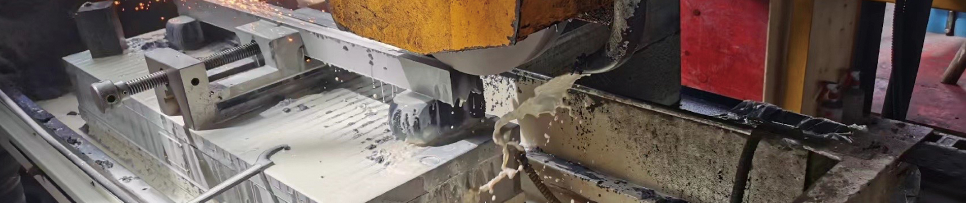

An engineering and purchasing guide to upper slitter knives, lower slitter knives, paired shear cutting, dimensional accuracy, troubleshooting, and custom replacement specifications.
A rotary slitting line is only as reliable as the relationship between its cutting tools. One knife may have an excellent steel grade, a beautifully polished edge, and a precise bore, yet fail to produce acceptable strips when it is paired with the wrong mating component. Paper edges become fuzzy, plastic film stretches, aluminum foil tears, or steel strip develops excessive burrs. The immediate temptation is to buy a sharper blade. The more useful response is to ask whether the upper knife, lower knife, holder, arbor, and substrate are working as a coordinated cutting system.
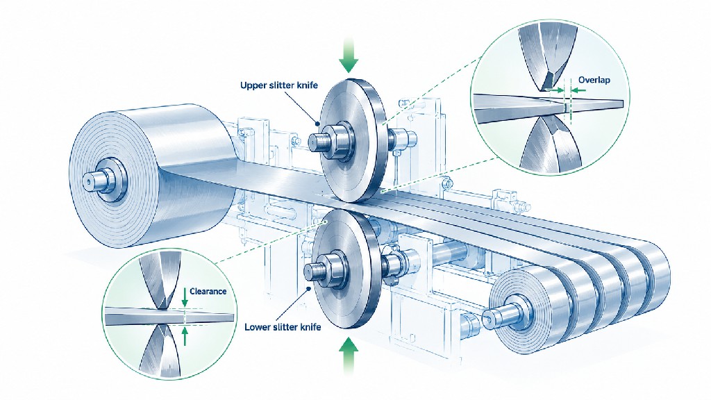
Top and bottom slitter knives are normally used together in rotary shear slitting. The top or upper knife establishes an active cutting point against a bottom or lower knife, anvil ring, or grooved counter-knife. The cutting pair behaves rather like continuously rotating scissors, but the actual contact zone is governed by the blade profiles, side relationship, penetration or overlap, shaft alignment, and the moving material. The lower knife is not simply a passive support: its position, edge condition, concentricity, and stiffness help determine whether every revolution produces the same clean slit.
This guide is written for converting plants, metal service centers, slitter-rewinder operators, original equipment manufacturers, spare-parts distributors, and purchasing engineers. It explains what each knife does, how to read its geometry, why web-converting settings should not be copied onto metal-coil equipment, and how to specify a shear slitting knife set that can be inspected, installed, maintained, and reordered consistently. Where numerical values appear, the article distinguishes published manufacturer examples from calculations and project-specific acceptance requirements. No single blade angle, gap, overlap, or hardness is suitable for every machine.
GUANG CHUAN supplies precision industrial machine knives and customized cutting solutions. Buyers assessing the actual product family can examine its industrial top and bottom slitter knives for paper converting machinery and the broader circular slitting and rewinding blade category. This article concentrates on how an upper and lower knife function together rather than treating the two parts as unrelated consumables.
Quick answer. An upper slitter knife usually provides the sharp, accurately presented shearing edge; a bottom slitter knife or anvil ring provides the mating cutting edge and a controlled contact reference. A dependable pair requires compatible edge geometry, matching rotation and hand, suitable overlap and side relationship, controlled runout, and a validated setup for the actual material. Buy the pair by drawing and cutting performance, not by outer diameter alone.
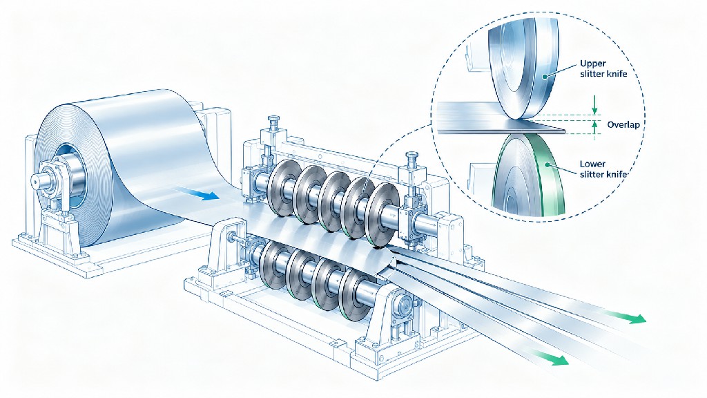
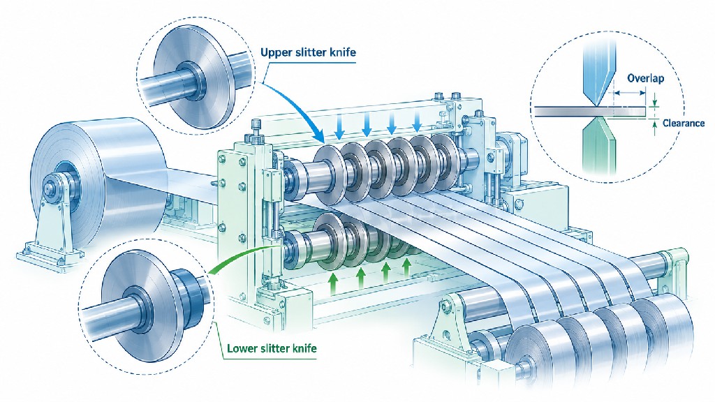
The phrase describes a functional arrangement, not a universal catalog standard. Top slitter knives and upper slitter knives usually mean circular cutters mounted above the material path or on the upper shaft of a slitting machine. Bottom slitter knives and lower slitter knives usually mean mating circular cutters, anvil rings, or grooved cutting components positioned below the web or on the lower shaft. On some machines, the entire knife module is tilted, inverted, or arranged horizontally. In those cases, top and bottom describe the equipment maker's component designation rather than gravity alone.
In a conventional shear slitting system, two cutting edges move past one another with controlled geometric engagement. The incoming sheet or web is locally deformed and separated at a narrow cutting point. The process differs from razor slitting, in which a very thin knife cuts through material, and from score or crush slitting, in which a blade is pressed against a roll. Those processes may all use circular tools, but they apply different loads and need different replacement parts.
The industrial slitting specialist DIENES describes shear cutting as a process based on overlapping knives and identifies several arrangements: two continuous shafts, a continuous bottom shaft with individual upper holders, and systems with individually driven lower knives. That variety explains why a photograph of a circular disk cannot establish what component the buyer actually needs.
| Catalog name | Usual meaning | What still must be checked |
|---|---|---|
| Upper slitter knife / top slitter knife | Active circular knife in the top position or holder | Bevel orientation, diameter, thickness, bore, mounting hand, usable regrind diameter |
| Lower slitter knife / bottom slitter knife | Mating circular cutting element on bottom shaft | Cutting face, groove or shoulder, bore, spacer relationship, runout, drive configuration |
| Male knife / dished knife | Traditional name for certain upper knife shapes | Whether the OEM actually uses that profile and naming convention |
| Female knife / anvil knife | Traditional name for certain bottom cutting rings | Whether the ring is grooved, flat, multi-edge, or a separate driven component |
| Shear slitting knife set | Compatible group of upper and lower knives and sometimes spacers | Whether both members and all necessary mounting parts are included |
| Rotary slitter blade | Broad description of a rotating cutter | Whether it is designed for shear, razor, score, or another cutting method |
Names vary between machine manufacturers and countries. To prevent a wrong-order dispute, the purchase drawing should label the actual cutting face, machine direction, rotation, side of the strip to retain, and the mating part number. A right-hand knife can be visually similar to a left-hand knife while presenting its bevel on the wrong side of the slit. The separate GUANG CHUAN explanation of circular slitter blades versus rotary slitter knives covers catalog naming in greater detail.
Visualize a continuously moving paper web entering a slitter rewinder. The lower knife rotates with a driven shaft or anvil ring. A top knife, carried by a precisely located holder, engages the lower edge at a controlled point. The material approaches the junction; the opposed edges apply localized stress; and a narrow line of material separates into two lanes. Both parts must remain correctly aligned while the web travels, the rolls turn, and the machine warms up.
This is not the same as allowing two sharp disks to collide. The cutting faces meet, pass, or run with a designed lateral relationship according to the machine type. Correct cutting takes place at the intended contact or shear zone. Excessive rubbing over a wide surface can destroy the edge even if it makes the material separate for a short time. The practical objective is enough stable engagement to shear the substrate, with as little unnecessary contact as possible.
The top knife typically contributes the sharpened bevel and a localized shear point. It may be spring-loaded, pneumatically engaged, or mounted in a fixed collar. The bottom knife often contributes a stable reference edge or shoulder. In other designs both tools have meaningful cutting bevels. Therefore, there is no safe assumption that a replacement upper and lower knife will share the same profile, thickness, material, or heat treatment.
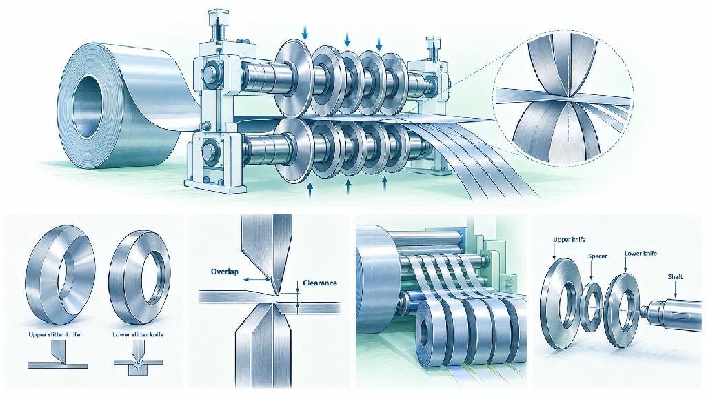
Dual-shaft slitting: Multiple knife sets and accurately ground spacers are assembled on upper and lower arbors. The spacers determine lane widths, knife positions, and sometimes lateral clearances. Shaft bending, stack cleanliness, clamping force, and spacer accumulation can all alter the result. This architecture appears in many metal-coil and heavy-duty strip applications.
Individual upper holders against a common lower shaft: Each upper blade is carried in an adjustable holder while a continuous lower shaft supports rings or anvils. This is common in web converting, including paper, labels, and film. A holder may allow separate depth, cant-angle, and side-load adjustments. Fast position changes are possible, but every holder must reproduce the intended geometry.
Modular or separately driven knife units: Top and/or lower knives can be housed in individual units, sometimes with their own drives. These arrangements may suit high-value webs or frequent width changes. They can reduce certain shaft limitations but demand attention to speed matching, bearing condition, controls, and module alignment.
Machine choice influences knife specification. For example, DIENES notes that in some pneumatic holders a top knife rotates by frictional engagement with the driven lower knife, and that sensitive webs can justify positively driven cutting solutions. A tool quotation should therefore identify not just the substrate and knife diameter but also whether the upper knife is driven, freely rotating, or contact-driven.
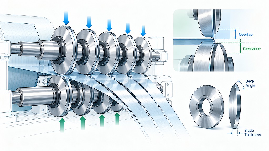
The upper knife has a demanding task: establish a sharp, repeatable cutting point while tolerating the actual holder force and rotation. In many paper-converting systems it is a dished circular blade with a relatively thin edge; in other systems it is flat or has a specialized shoulder. The correct geometry depends on which face touches the lower knife and where the separated material must travel after cutting.
A steep or robust bevel may improve local edge strength but can influence how the material deflects. A very acute bevel can cut with low resistance yet become susceptible to chipping or rapid wear if excessive side force is applied. Neither observation creates a universal preferred bevel angle. A qualified knife supplier should inspect the existing part, the mating knife, the holder, and the substrate before proposing a new profile.
A dished knife removes much of the blade body from the immediate shearing region, leaving a narrow cutting land. That can reduce unwanted rubbing when the application is designed for this geometry. A flat top knife uses a different stiffness and mounting arrangement and may be preferred where holder geometry or service practice requires it. Narrow blades, beveled rings, and custom mounting cartridges can be appropriate for special slitting machines.
The important buying distinction is not whether the knife looks sophisticated. It is whether its effective cutting edge occupies the intended axial plane after the blade has been clamped. A change in dish depth, plate thickness, or bevel width can shift that plane even when the outer diameter and bore remain identical. The result may be excess side load, loss of contact, unstable slit width, or premature wear of the lower edge.
For a symmetrical replacement, operators can sometimes flip a blade. For an asymmetric top knife, flipping may put the cutting face in the wrong position. The drawing must show the blade as viewed from the operator side, together with the direction of rotation and the intended contact face. This becomes essential where adjacent slit lanes use opposite-handed knives, where scrap trim has a dedicated exit path, or where the cutting head is mounted from the opposite side of the machine.
When reviewing a new upper knife, inspect the land width, bevel continuity, edge condition, axial face, mounting diameter, seating flatness, and any locating holes. Ask whether the tool can be reground and which dimensions will change during regrinding. A small difference in regrind history can become a major setup issue when multiple holders share one height setting.
The lower knife is sometimes treated as a hardened support for an upper knife. That description is incomplete. Its cutting edge, axial face, diameter, groove geometry, and mounting accuracy determine the location and consistency of the shear point. A lower ring with noticeable face runout can periodically push against the top knife. That repeated impact may appear to the operator as ordinary blade dulling, when the real cause is eccentric or tilted tooling.
Flat lower rings, cup-shaped anvils, groove-based bottom knives, and multi-groove knife blocks offer different mating surfaces. Some give one active edge; others provide multiple edge positions. A grooved ring may allow several upper knives to interact with defined shoulders. However, groove pitch and groove depth must be matched with upper-knife position and the desired lane widths. It is not enough to say that both components are made from the same steel.
A multi-groove bottom slitter can simplify repeated width arrangements, but it also introduces additional dimensional relationships. Groove-to-groove pitch, shoulder width, side-face parallelism, groove-bottom clearance, and cumulative machining error affect the finished lanes. If a stack is used, the assembly can also be sensitive to spacer tolerances and trapped contamination between rings.
The product range at GUANG CHUAN includes top-and-bottom slitter knife assemblies and product examples involving multi-groove bottom cutters. A custom order should include the complete profile drawing and indicate which surfaces are functional, instead of specifying only outside and inside diameters. That drawing helps prevent an expensive situation in which every delivered part passes a simple diameter check but none runs acceptably in the machine.
The lower knife's larger contact body or different cross-section may justify a different material and hardness from the upper blade. The choice should be based on the wear pattern and load at the actual contact zone. Replacing a damaged lower ring without checking the upper blade can transfer the fault immediately to the new component. Where both have visible chips, regrinding one part and continuing with the other may shorten the life of the repaired set.
Good shear slitting depends on several independent geometrical relationships. Operators often discuss them under one phrase, such as “knife setting,” but changes to one parameter cannot automatically correct another. This distinction is particularly important in technical procurement: a blade can be machined accurately and still fail because the installed machine geometry is wrong.
| Parameter | Plain-language meaning | How it is normally controlled | Common result when wrong |
|---|---|---|---|
| Overlap or engagement depth | How far projected upper and lower cutting circles overlap | Holder depth, arbor center distance, machine recipe | Missed cut, dust, edge rubbing, premature wear |
| Lateral clearance or face relationship | Side-to-side position of the active shear faces | Precision spacers, holder motion, axial shaft positioning | Burrs, folded edges, knife rubbing, inconsistent fracture |
| Side force | Force pushing mating cutting faces into their intended relationship | Spring or pneumatic holder, collar, force setting | Excessive edge wear or loss of stable contact |
| Cant or shear angle | Small designed angular relationship at the contact point | Knifeholder key, mounting geometry, machine design | Unstable cutting point, rubbing or edge distortion |
| Radial runout | How much the cutting circumference moves in and out during a revolution | Knife machining, arbor fit, bearings, mounting | Intermittent contact or varying overlap |
| Axial face runout | How much a functional face wobbles sideways during rotation | Face grinding, flange seating, arbor alignment | Periodic force changes, scratches, knife damage |
| Parallelism and stack accuracy | Whether opposed shafts or faces maintain the designed relationship | Machine alignment, spacers, clamping and clean assembly | Lane-to-lane variation, drift in slit width |
In many tangential web slitters, overlap is measured as the distance by which the upper knife extends below the tangent of the bottom knife. It is a geometric engagement of the two circular cutting envelopes, not the depth a blade has physically penetrated into a thin film. For example, a holder may have substantially more than the film's thickness of geometric overlap without the knife literally plunging that distance through the material.
DIENES explains the role of overlap in maintaining the cutting point and controlling the length of web contact along the knife bevel. Its discussion cites approximately 0.030–0.040 inch, or 0.76–1.02 mm, as a reference for many of its shear-cut applications. This is not a global setting recommendation. It reflects a particular family of converting setups and must not be transferred automatically to ultrathin foil, another holder design, or steel-coil slitting equipment.
For a detailed treatment of why over-engagement can produce debris and why the OEM reference datum matters, read the related GUANG CHUAN guide to slitter knife overlap. The present guide focuses on the interaction between both knives as a purchasing and installation system.
In a metal-coil line, horizontal clearance often means the intentional lateral gap between opposing shear edges. Its required value depends on material thickness, strength, ductility, edge-quality target, tooling stiffness, and line condition. A percentage-of-thickness calculation may be used within a specific metal slitting procedure, but one must define whether the drawing calls for a single side gap or total combined clearance. Misunderstanding that difference can double the intended setting.
As an arithmetic illustration only, an individual side gap of 0.025 mm on a 0.50 mm strip equals 5% of strip thickness: 0.025 ÷ 0.50 × 100 = 5%. That does not mean 5% is the correct setting for all 0.50 mm metal. An engineer must validate the value against material grade, machine data, and the resulting cut edge. In a contact-loaded paper web slitter, there may be no comparable intentional positive lateral clearance at the cutting point. Copying a metal-coil formula into a pneumatic paper knifeholder is therefore a category error.
A cant angle establishes a small angular approach between the interacting blade faces. It can concentrate the cut into a useful point rather than allowing a broad face-to-face contact region. The correct direction and angle follow the holder design and web path. DIENES USA describes one-quarter, one-half, and three-quarter degree configurations in its converting discussions, with a half degree commonly used in the applications it addresses. Those values should be understood as manufacturer examples, not as instructions for every slitter.
Side pressure or side loading is the force that maintains contact where the holder requires it. Excess force can accelerate blade wear, while inadequate contact can let the cutting point wander. An air-pressure gauge may not directly measure force at the edge because piston area, springs, friction, wear, and linkage geometry affect the result. Use the manufacturer's specified force-verification method. Increasing the regulator pressure to overcome a loose holder or damaged bearing is not a substitute for machine repair.
Material grade matters, but it matters after the cutting method and dimensions are established. The most expensive alloy does not compensate for an inaccurate shaft or unsuitable bevel. A replacement upper blade can wear quickly against a much harder lower ring; a lower ring can chip if the upper knife delivers concentrated impact at the wrong edge. Matching is therefore about complementary behavior, not necessarily using identical steel for both tools.
AISI D2-type cold-work tool steels, M2 high-speed steels, cobalt-bearing M42, and selected tungsten carbide grades are among the candidates encountered in industrial slitting. The best choice depends on abrasion, contact pressure, substrate contaminants, impact risk, desired regrind interval, and the ability of the operating team to handle the edge safely. Material certification and finished-hardness verification are useful, but neither certifies that a tool will deliver a predetermined number of production hours.
| Material family | Reasons a buyer might consider it | Important limitations | Evidence to request |
|---|---|---|---|
| D2 / SKD11-type tool steel | Established industrial option with good abrasion resistance and familiar grinding practice | Edge chipping risk under poor alignment; not immune to corrosion | Certified material designation, heat treatment, finished hardness, microstructure if required |
| M2 high-speed steel | Balanced choice where sustained abrasive duty or edge stability warrants higher material cost | More expensive than basic tool steel; incorrect setup still causes damage | Grade confirmation, heat-treatment condition, edge finish and comparative trial |
| M42 cobalt high-speed steel | Candidate for selected demanding wear or elevated-temperature applications | Premium cost; higher hardness alone does not ensure better toughness or economics | Trial results against M2, complete quality and regrinding plan |
| Cemented tungsten carbide | Potentially strong abrasion resistance for controlled, high-volume or abrasive work | Brittle edge and impact sensitivity; grade and binder selection are critical | Exact carbide grade, toughness/wear data, edge preparation, handling and grinding procedure |
Hardness figures require context. HRC values are useful for appropriately hardened steels, while many cemented-carbide suppliers use HRA or Vickers scales. Such numbers are not directly interchangeable as simple rankings. When hardness inspection is specified, ISO 6508-1:2023 provides a recognized test-method reference for Rockwell hardness of metallic materials. A buyer still needs to define the actual location, number of tests, acceptable range, and whether the finished knife geometry permits a valid measurement.
A tool's heat-treatment sequence also affects dimensional stability. Vacuum processing, controlled tempering, and optional cryogenic steps may be used in specialized manufacturing, but marketing descriptions of those processes are not proof of a universal life improvement. Ask the supplier what property a proposed treatment is intended to improve and how the result will be verified. If a premium treatment produces a longer interval between sharpening but also increases edge chipping, the net cost may be worse.
The existing GUANG CHUAN comparison of D2, M2/M42 HSS, and tungsten carbide slitter knives provides a deeper discussion of material trade-offs. For a paired set, request that the supplier recommend and document both the upper and lower materials together. An otherwise sensible upper-material upgrade can fail when the lower ring remains damaged or is incompatible with the new contact load.
Two circular knives may share an outer diameter and still be completely incompatible. The central bore, actual blade thickness, effective edge position, dish or groove profile, and mounting face determine the way each component seats. A keyed bore is not interchangeable with a plain bore if the original shaft needs positive rotational location. A nominal thickness measurement taken at the thickest body section may not describe the cutting land accurately.
A good replacement drawing starts with a common datum system. Define the mounting bore or spindle axis, the seating face, and the functional cutting edge. Then put the tolerances on the surfaces that affect performance. A blanket statement such as “high precision” makes it difficult to inspect incoming goods, diagnose a mismatch, or resolve a commercial claim. Tolerances should follow the machine's actual needs; unnecessarily tight requirements on nonfunctional surfaces raise price without improving the slit.
| Drawing item | Why it matters | Recommended way to specify it |
|---|---|---|
| Outside diameter (OD) | Affects circumferential position, overlap and available regrind reserve | Nominal diameter, tolerance, min. permissible reground diameter |
| Bore / inside diameter (ID) | Establishes concentric location on arbor or holder | Nominal fit, tolerance, shaft mating details, datum reference |
| Body thickness and edge position | Determines axial engagement and slit lane geometry | Thickness at named locations, functional cutting face, axial offsets |
| Bevel, dish or edge-section geometry | Defines contact area and direction of shear | Section drawing with angles, radii, land widths, hand and orientation |
| Groove profile or shoulder | Governs mating upper-knife engagement | Groove width, depth, pitch, tolerance, edge location and groove sequence |
| Radial and axial runout | Prevents cyclical change in knife engagement | Maximum indicator reading, measurement datum, inspection fixture |
| Flatness and face parallelism | Improves consistent seating and stack accuracy | Which functional faces, inspection method and maximum permitted deviation |
| Material and finished condition | Controls wear, edge stability and regrinding behavior | Grade, treatment, specified hardness/test scale and traceability |
| Keyway and mounting features | Preserves positive location and correct assembly | Size, angular location, hole pattern, chamfers and burr limitations |
| Marking and regrinding limits | Keeps matched components identifiable | Part number, set number, hand, diameter group and revision |
A published GUANG CHUAN top-and-bottom slitter knives product specification lists a customizable outside-diameter range of 50–500 mm, a 58–62 HRC hardness range for its stated steel-tooling configuration, and examples of 0.003 mm flatness/parallelism and 0.005 mm runout. These are supplier-published product figures, not industry-wide requirements and not blanket guarantees for every size, material, or customized part. Buyers should request a drawing-specific quotation, state the exact inspection datum, and confirm which values apply to the proposed finished upper and lower knives.
For instance, a 0.005 mm radial runout target means little unless the supplier and buyer agree whether it applies to the free component, a knife mounted on a reference arbor, or the actual assembled machine. A perfectly ground knife installed on a dirty flange can show far greater assembled runout. Conversely, a complete ring can perform adequately on a given application even when a very tight catalog figure is not necessary. Fit-for-purpose inspection is more useful than numerical precision as a sales slogan.
In multi-lane slitting, the final slit width is not determined by blade diameter alone. Spacers, shims, clamping faces, shaft location, and the effective position of each cutting edge establish the spacing. If a line uses many rings, small thickness deviations can accumulate across the shaft. Those accumulated errors may appear as one lane being too narrow while another is too wide. The technician may suspect the knives even though the spacers or clamping arrangement are responsible.
Keep mating faces clean, distinguish precision spacers from ordinary washers, and measure the final assembled stack against the drawing. Avoid mixing sets that have different regrind histories unless the machine has independent adjustment sufficient to compensate. A good supplier should help identify which spacers, collars, rubber stripper rings, or other components are necessary for a complete conversion or replacement package.
The correct setup sequence depends on the machine's original equipment manual. The procedure below is a commissioning framework, not a substitute for the OEM's safety, torque, locking, pressure, or alignment instructions. Knives are sharp even when stationary. Only authorized personnel should handle the tooling, and the line should be isolated and secured under the site's lockout/tagout procedure before exposure to hazardous motion.
1. Identify the exact knife system and record the baseline. Before taking anything apart, record the machine model, holder type, upper and lower part numbers, dimensions, blade orientation, current diameter, operating material, nominal slit width, and the defect that motivated service. Photograph the original mounting relationship and label all components. If the existing line is still producing acceptable material, its validated settings form a useful reference.
2. Inspect both knives rather than replacing one blindly. Look for chipped edges, rounded cutting lands, abnormal wear bands, scratches, adhesive buildup, cracked carbide, and damage around the bore. A sharp upper blade against an eccentric or nicked lower knife may immediately reproduce the original problem. Check that matching faces and wear patterns are consistent with the design.
3. Inspect the mechanical support. Clean and inspect the arbor, flange, bearing condition, mounting faces, holder slides, clamping collars, and reference surfaces. Confirm that a holder has no abnormal looseness and that the shaft turns without unexpected radial or axial movement. If the machine itself is unstable, a knife change may make a temporary cosmetic improvement while leaving the root cause intact.
4. Assemble in the correct hand and sequence. Install the knives, spacers and required rings in the orientation specified by the drawing. Verify the functional edge is where it belongs. Protect cutting edges from contact with hard tools, nearby machine structure, and adjacent blades while assembling. Apply specified fastener tightening and shaft clamping methods; do not invent torque values.
5. Verify the installed geometry before production. Measure the relevant OD, contact-face location, runout, and seating condition using appropriate calibrated instruments. Check that every upper knife aligns with its intended lower edge. A pre-set holder or CNC readout should be treated as a positioning aid unless its actual cutting geometry has been independently validated.
6. Establish the OEM-approved starting overlap and lateral relationship. Enter the validated recipe for the actual substrate and tooling combination. If no approved recipe exists, plan a controlled trial with process engineering and the machine supplier. Do not increase overlap or side force merely because the first sample looks incomplete; check whether the problem is caused by wrong hand, damaged mating faces, material flutter, or misalignment.
7. Perform a guarded low-speed trial. Once the machine is ready under its prescribed safety process, run representative material at an approved reduced speed. Inspect the cut, winding behavior, lane widths, and noise or vibration. Check both sides of the separated web or strip. A clean-looking edge on one lane is not proof that every knife pair is performing correctly.
8. Move to the production range and verify stability. Record results at the approved production speed and, where relevant, after the equipment reaches operating temperature. Test the worst practical width arrangement and relevant coil or web tension range. The best setting is the one that remains stable, not simply the setting that produces a good ten-second demonstration.
9. Release a controlled setup record. Save the final tool numbers, set numbers, measured dimensions, holder settings, inspected edge outcomes, line speed, substrate specification, and date. Make that record available to both maintenance and purchasing personnel. Repeatability is the real commercial value of a good upper/lower knife system.
For a separate breakdown of clearance, overlap, and side-load interactions in flexible webs, use the GUANG CHUAN setup guide for paper, film and foil. That article is a companion reference, not permission to apply one generic setting across every machine.
A paper slitter rewinder, a plastic film converting line, a battery foil line, and a heavy metal service-center slitter are not mechanically identical. All may use paired rotating cutters, but their dominant failure modes differ. The material's deformation behavior and the machine's stiffness influence the knife geometry as much as nominal thickness does.
Paper conversion commonly prioritizes clean fibers, low dust, dimensional stability, and consistent winding. Low basis-weight paper can flutter or tear if web tension is unsuitable. Heavier paperboard may require a different blade profile and more robust driving arrangement. Adhesives, fillers, mineral coatings, and recycled-fiber content can change abrasive wear and contamination at the knife edge. A top knife that appears dull after a short period may actually have accumulated coating material or encountered excessive contact with the lower ring.
On these lines, verify web path, tension, holder geometry, overlap, and the condition of the lower anvil. Sample edge fuzz and dust at consistent production speeds rather than choosing a setting solely from the operator's visual impression. The knife recommendation should specify the actual grade of paper, coating, grammage, thickness, and required cleanliness.
Thin flexible films can stretch instead of shearing cleanly if the cutting point is unstable. Elastic behavior, temperature, web tension, adhesive tack, and layer structure matter. A brittle coating may crack even when the base film remains intact. Labelstock may require controlled separation without unacceptable liner damage. For laminated webs, it is important to understand whether all layers are intended to separate or whether only selected layers should be cut.
These applications often benefit from a carefully adjusted upper blade and a stable lower anvil, but the exact shape and side relationship are holder-specific. Excessive overlap can increase contact with the blade body; inadequate engagement can allow web lifting and intermittent cuts. Ask the supplier to evaluate representative production material, including the hardest-to-process coating or adhesive combination.
Foil slitting demands high sensitivity to very small edge defects. Micro-burrs, folding, particle generation, waviness, and handling damage may be unacceptable in subsequent operations. The foil temper, thickness, surface finish, and line tension all influence the process. Edge inspection and dimensional control often matter more than a visually dramatic “sharpness” claim. The machine may need tight runout control and an appropriately fine edge preparation, but the correct tolerances must be demonstrated against the specified acceptance limit.
Avoid assuming that the knife package used on a paper rewinder will fit a precision foil line. Even where similar outer diameters appear in the catalog, the cutting profile, holder stiffness, drive design, and inspection criteria may be different. A sample-based qualification program is usually more credible than selecting a carbide or HSS grade solely from a material table.
Metal-coil slitting imposes much higher deformation loads than many flexible-web applications. Lateral knife clearance, shaft deflection, strip tensile properties, stripper-ring support, stack design, and coil shape are major inputs. The slit edge may display rollover, a burnished zone, a fractured zone, and a burr. Operators often inspect these zones to understand the cut rather than attempting to eliminate every feature entirely.
Technical discussions of metal slitting edge development identify material thickness and tensile properties, equipment condition, and horizontal clearance as influential factors. That does not make a patent a factory setting chart. It illustrates why a number suited to low-strength steel may be unsuitable for stronger or differently tempered strip of similar thickness. For an existing quality problem, the GUANG CHUAN article on reducing burrs when slitting metal coils offers a more focused troubleshooting route.
| Application | Main edge-quality concern | Key setup checks | Information a supplier needs |
|---|---|---|---|
| Uncoated paper | Fibers, dust, irregular winding | Top/lower contact, holder cant, tension, dullness | Grade, grammage, caliper, web width, speed |
| Coated paper / labels | Adhesive or coating pickup, frayed edges | Edge contamination, anvil finish, web path, blade profile | Coating, adhesive, liner, target edge cleanliness |
| Plastic film / laminates | Stretching, folding, layer damage | Minimal effective overlap, tension, speed, knife geometry | Polymer type, film thickness, layer structure |
| Aluminum / copper foil | Micro-burrs, fine particles, edge folds | Runout, cutting-point stability, material temper | Thickness, temper, defect criteria, magnification method |
| Metal coil / strip | Burrs, camber, edge wave, dimension drift | Lateral clearance, stack, shaft deflection, knife condition | Grade, thickness, strength, width schedule, burr limit |
These are engineering priorities, not universal setting values. Within one row, a change in coating, hardness, temper, or line design may alter the recommended knife dramatically. The most useful technical inquiry describes the operating problem and the acceptance target, not merely the substrate name.
Slitting faults are often blamed on whichever part was replaced most recently. A better troubleshooting process connects the visual defect to a measurable mechanical condition. First classify the defect; then isolate one likely cause at a time. Do not simultaneously increase pressure, deepen overlap, replace the upper knife, and change the web tension: if the result improves, no one can identify which action was responsible.
| Symptom | Possible knife-pair cause | Other causes to eliminate | First controlled check |
|---|---|---|---|
| Fuzzy or feathered paper edge | Worn upper edge; excessive overlap; wrong cant | Web flutter, coating buildup, winding tension | Inspect bevel and lower contact; compare validated holder setting |
| Intermittent uncut sections | Too little stable engagement; chipped edge | Runout, holder movement, web variation | Check installed runout and engagement across rotation |
| Persistent burr on metal strip | Inappropriate lateral clearance; rounded edge | Material strength, shaft deflection, stripper condition | Examine both slit edges and recorded clearance recipe |
| Edge scratches or scuff lines | Excessive rubbing on upper or lower face | Path geometry, debris, transport contact | Inspect wear marks and look for unintended blade-body contact |
| Very short upper-knife life | Excess side force; lower anvil damage | Loose holder, wrong grade, wrong bevel | Measure side-load method and lower-face runout |
| Repeating vibration or chatter | Inaccurate concentricity or axial wobble | Bearings, drives, shaft support | Measure runout at installed operating surfaces |
| Variable slit width among lanes | Mislocated cutting edges or mismatched spacers | Web tracking, thermal expansion, clamping | Check full stack dimensions and lane map |
| Edge wave or strip camber | Poor cutting geometry or uneven knife loading | Incoming coil shape, tension, material residual stress | Inspect edge asymmetry and machine alignment |
Manufacturers of slitting systems consistently emphasize the geometry of the cut rather than blade sharpness alone. For example, DIENES identifies cut-point position, cant angle, overlap, and dimensional runout as major influences on shear quality. That is a useful diagnostic framework because it separates the cutting surface from the machine features that control it.
Check repeatability before changing materials. A defect that occurs once per revolution suggests a rotating geometric or surface condition. A defect that occurs only at full production speed may involve dynamic stiffness, vibration, drive synchronization, or tension. A defect that appears after several hours may suggest wear, temperature, adhesive buildup, or gradual loosening. Recording when the problem appears can shorten the troubleshooting process more effectively than buying an exotic blade grade.
Inspect a meaningful sample. For a wide web, include edge trim and interior lanes. For a metal coil, inspect strips from different positions across the width and, where relevant, from the beginning, middle, and end of the run. Use the customer's actual method for measuring burr height, particles, dimensional accuracy, or edge roughness. A magnified image without a stated scale is useful for discussion but weak as formal acceptance evidence.
Regular inspection is more economical than waiting for a knife to fail catastrophically. A rounded edge may slowly increase dust or burrs. A chipped edge can immediately damage material or the mating knife. The maintenance threshold should therefore be based on an acceptable product-quality limit and a controlled tool condition, not on a fixed number of days printed in a catalog.
Regrinding removes material and changes blade geometry. On a top knife, a reduced outside diameter can change the overlap available from a holder. On a bottom knife, regrinding can change edge location, effective diameter, or the width of a contact land. If a multi-groove ring is reground incorrectly, the groove pitch may remain unchanged while the profile of its active shoulders becomes unsuitable for the upper knives.
A matched set should have a documented minimum usable diameter and an approved edge profile. After grinding, the supplier should verify that the required contact surface, bevel, bore reference, and runout remain within specification. Knives with different outer diameters can sometimes operate in independently adjustable positions, but mixed sizes on a common setting may cause uneven engagement. Color coding, set identification, or individual inspection sheets help prevent accidental mixing.
DIENES discusses the need to readjust depth after regrinding, because the outside diameter changes as material is removed. That is a practical reason to specify both the original dimension and the final discard dimension. The GUANG CHUAN guide to deciding when circular slitter knives need sharpening or replacement examines that maintenance decision further.
Prevent contamination and handling damage during storage. Protect edges individually, avoid stacking bare cutting faces together, and label part orientation. Steel blades may need appropriate corrosion protection; carbide edges need protection against impact. Inspect tools after transport and before installation. A small nick introduced by careless handling can become the apparent “factory defect” discovered on the first production run.
A purchaser may save money by ordering only the visibly damaged upper blades. Sometimes that is exactly the correct choice. However, a new upper knife can wear rapidly against a worn lower ring, and an incompatible replacement can shift the shearing point. Ordering a coordinated set becomes attractive when the old components are untraceable, the lower knife is damaged, the OEM profile has changed, or the plant wants to standardize several machines.
Set procurement also improves communication. Instead of two suppliers arguing over whose individual knife is correct, one technical package can define the edge relationship and the inspection method. The purchase order can name the upper part, the lower part, optional spacers, functional drawings, set marking, measurement records, and the quality outcome expected from an agreed production trial.
That does not mean every upper and lower component should always be replaced together. The commercial goal is the lowest verified cost per accepted unit of output. If the bottom knives remain dimensionally sound over several upper-knife sharpenings, keeping them may be sensible. Conversely, if an older lower anvil drives premature top-knife wear, replacing the lower component can lower total cost even when the new lower ring looks expensive.
Consider the following hypothetical illustration, which is not a claim about GUANG CHUAN products or any measured slitting line. The plant compares two maintenance options at the same edge-quality threshold. The estimated downtime cost assumes the same planned change duration for both options. Values are shown only to demonstrate how buyers can structure a decision.
| Illustrative cost element | Option A: basic replacement | Option B: premium paired set |
|---|---|---|
| Tool purchase allocated to this service interval | $120 | $230 |
| Inspection/regrinding expense | $25 | $35 |
| Changeover downtime cost | $75 | $75 |
| Setup scrap and edge-quality loss | $20 | $20 |
| Total attributable cost | $240 | $360 |
| Accepted operating hours before next service | 60 h | 100 h |
| Attributable cost per accepted hour | $4.00/h | $3.60/h |
Option B costs more to acquire but is cheaper per accepted hour in this assumed scenario. Change the downtime, scrap, or service interval and the result may reverse. If the line already changes format every shift, an extra-long knife life may deliver little benefit. On a continuous high-speed line where a tool change causes hours of lost production, improved service interval can justify a significant premium.
For a real tender, use a common formula: cost per accepted output = (allocated tool cost + regrinding + changeover labor + lost-production cost + quality losses) ÷ accepted meters, tonnes, or hours produced. The denominator must be consistent between options. Maintain a separate record for accidental tool collisions, which should not be confused with normal wear life. This structure encourages suppliers to explain how their knife profile, material, and tolerance proposal creates measurable business value.
An effective request for quotation helps a manufacturer design and price a suitable replacement without a long sequence of speculative emails. A photograph can show the knife family, but it rarely provides complete bore tolerances, cutting-hand information, or inspection criteria. A physical sample helps with reverse engineering, but it may be worn and may not represent original geometry. Drawings, parts, and operating data work best together.
A good RFQ includes the following information:
A buyer does not need perfect engineering drawings before the first inquiry. It is acceptable to submit photographs and available dimensions and ask what else is needed. What matters is identifying unknowns openly rather than silently converting guesses into tolerances. A capable supplier should distinguish catalog information from custom drawing commitments and should flag incompatible combinations before the purchase order is finalized.
GUANG CHUAN describes its manufacturing scope, customized blade work, grinding and heat-treatment capability on its company information page. Buyers can then submit their drawings, material information and project requirements via its contact and quotation page. Supplying both knife roles in a single inquiry is particularly helpful where the machine has unusual groove geometry or an undocumented replacement history.
A supplier quotation and an inspection report should refer to the same drawing revision. Incoming quality control should verify identity first: correct part numbers, set numbers, quantity, material, orientation, and protective packing. Next inspect the functional dimensions and surfaces. Finally, where the contract requires it, validate the tooling in the machine using representative production material. These are separate acceptance stages; passing one does not automatically pass all three.
For dimensional inspection, the exact fixture and reference surface matter. A report stating “runout 0.005 mm” without the datum or measuring arrangement is difficult to reproduce. The same concern applies to parallelism, edge-section angle, and surface finish. Suppliers and buyers can use established metrology language to avoid ambiguous drawings. If a surface-texture parameter is specified, for example, ISO 21920-2 identifies a standardized vocabulary of profile surface-texture parameters. Such standards help define measurements; they do not prescribe one universal slitter edge finish.
A production acceptance trial should document substrate identity, web or strip width, thickness, holder setup, line speed, and number of lanes. Check edge quality against a previously agreed sample or measurement method. Verify that the result remains stable across the intended operating range. Photograph defects with scale information, label the sample location, and save measurements in the qualification record. If a trial fails, document whether the apparent cause is the knife, a spacer, machine setup, or incoming material rather than assigning blame based on purchase order alone.
| Acceptance level | What is evaluated | Typical documentary evidence | Responsibility to agree in advance |
|---|---|---|---|
| Documentation | Drawing revision, part identity, material designation | Approved drawing, packing list, material certificate | Buyer and supplier |
| Component geometry | OD, bore, thickness, edge profile, face/runout requirements | Dated dimensional inspection record | Supplier, with agreed measurement datums |
| Tool condition | Chips, surface damage, finish, marking and preservation | Visual or magnified inspection, labeled photos | Supplier and incoming QC |
| Assembly fit | Seating, hand, spacer stack, installed runout, correct holder engagement | Installation checklist and measured assembly data | Machine owner, optionally with supplier support |
| Production performance | Edge defects, slit width, scrap level, stability at agreed speed | Signed trial report and representative samples | Buyer, machine OEM, and supplier as contracted |
The final responsibility split should appear in the purchase contract. A knife supplier can control delivered tool geometry and material; the machine owner typically controls installed alignment, tension, operating condition, and material quality. Where a turnkey tooling package is purchased with installation support, responsibilities can be expanded by agreement. Clear boundaries protect both parties and make corrective action faster.
Ordering by outer diameter alone. A familiar 100 mm or 150 mm disk may have the wrong bore, thickness, bevel orientation, or lower-ring profile. Always compare the functional edge-section drawing and mounting interface.
Assuming upper and lower tools are interchangeable. A bottom knife may be thicker, grooved, or shaped to carry a contact surface rather than the thin active bevel of the upper knife. Swapping roles can damage tooling or create unsafe cutting behavior.
Using a steel-coil clearance value on a web converting holder. Clearance terminology differs between systems. Record whether the machine uses a controlled lateral gap, contact side load, or another geometry. Define the measurement before specifying a number.
Quoting maximum hardness as a performance guarantee. Edge stability comes from the material, heat treatment, geometry, contact load, and machine condition together. Verify the failure mechanism before proposing a more expensive alloy.
Ignoring the lower knife during repeated top-knife failures. A worn or eccentric anvil can destroy multiple new upper blades. Inspect the pair and the holder as a system.
Mixing new and reground blades without checking effective diameter. Different diameters change engagement and may require independent holder adjustment. Maintain regrind records and identify matched sets clearly.
Treating supplier catalog tolerances as unconditional. Published precision values may apply to a defined product or manufacturing route. Request drawing-specific capability, test results, and an agreed acceptance method for a customized order.
Buying a full set without checking the existing stack. A complete set can be valuable, but it must include the correct spacers, shoulders, and mounting components where required. A missing 0.1 mm spacer can undermine a much more expensive set of knives.
Usually yes. Both terms generally refer to the upper cutting component of a paired shear slitter. However, terminology varies between equipment makers, and some machines are installed in nonvertical orientations. Specify the part by its functional position, drawing, and holder rather than relying entirely on the word “top.”
Frequently, but not always. In some web converting systems the bottom knife is called an anvil ring or female knife. In other machines it has its own sharpened edge, multiple grooves, or a special shoulder profile. A score-slitting anvil roll is not automatically interchangeable with the bottom knife of a shear slitting pair.
Not necessarily. They can experience different contact stresses, wear mechanisms, and impacts. Identical material may simplify procurement and sharpening for some applications, but a mixed-material system can also be justified. Specify the behavior required of each cutting surface and qualify the pair together.
There is no universal answer. The machine OEM's validated setting is the starting point. Published converting references can be useful context, but values from one holder or material should not be copied onto a different machine. Confirm the measurement datum and validate slit quality at operating speed. Metal-coil practices may use different engagement concepts and should be assessed separately.
No. Side pressure may be necessary in contact-loaded holders, but too much can increase rubbing, temperature, and wear. Too little may allow the cutting point to open. A measured, stable force and a correctly aligned holder are more reliable than increasing pneumatic pressure to overcome mechanical faults.
Yes, when the lower knife is dimensionally sound, undamaged, compatible with the new upper tool, and still within the approved service limits. Inspect the lower ring carefully. If repeated top-blade failures follow installation, investigate lower-edge condition and assembled runout before ordering additional top knives.
A flat knife and a dished knife position material and contact surfaces differently. A dished profile may help localize contact in a holder designed for it; a flat disk may offer a different stiffness and mounting arrangement. The correct choice is determined by the OEM configuration, functional cutting face, and substrate, not by appearance alone.
Possible reasons include excessive side force, too much overlap, unsuitable clearance, wrong blade hand, poor concentricity, contamination, abrasive coatings, bearing movement, and improper grinding. Inspect the mating lower component and holder before assuming the tool steel is defective. Compare failure patterns and accepted production output with a documented baseline.
Provide available drawings or samples, machine and holder details, upper and lower part orientation, OD/ID/thickness, profiles, substrate range, slit widths, operating conditions, and edge-quality requirements. Where measurements are missing, state that they are unknown so the supplier can recommend a measurement or sample-inspection process.
Absolute zero-defect promises are rarely a meaningful technical specification across variable industrial materials. A better approach defines the acceptable burr or dust limit, measurement method, sampling frequency, and production conditions. The supplier can then propose knife geometry and a qualification test against a measurable target rather than relying on an unqualified marketing claim.
A dependable shear slitting knife set is a matched mechanical relationship, not simply two circular pieces of tool steel. The upper knife establishes the active edge; the lower knife provides the designed mating edge and reference; the holder, arbor, spacers, and machine control preserve that relationship during production. When those factors are specified together, plants can reduce trial-and-error adjustments, improve cut consistency, and make spare-parts buying more predictable.
GUANG CHUAN offers precision industrial cutting tools and customizable top-and-bottom slitter knife configurations for paper, film, foil, and suitable metal-processing applications. For a practical starting point, review the top and bottom slitter knife product page. If you require an OEM-equivalent replacement or a nonstandard profile, share the drawings or worn samples, machine model, material data, quantity, and target cut quality using the GUANG CHUAN inquiry form.
Request a technical quotation with both knife roles specified. Ask for a matched upper/lower drawing, material recommendation, dimensional inspection scope, suitable regrinding limits, and an agreed verification plan. The most valuable knife is not automatically the hardest or cheapest one: it is the knife pair that produces acceptable material repeatedly at a sustainable total operating cost.

Leave A Message
Scan to WhatsApp :

 English