




Introduction
Burrs on slit metal edges can damage downstream tooling, interfere with welding or forming, create handling hazards and increase scrap. When burr height begins to rise, operators often replace the circular knives immediately. A dull edge may be involved, but the blade is only one part of the slitting system.
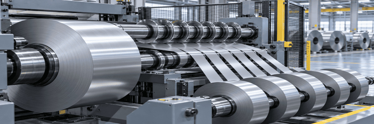
In rotary shear slitting, an upper and lower circular knife initiate deformation and guide the strip toward a controlled fracture. The final edge normally contains rollover, a bright burnished zone, a darker fracture zone and a small burr. The goal is not to chase an unrealistic “zero-burr” condition in every material; it is to keep the burr within the customer’s specification and consistent across every lane and throughout the coil.
Quick answer: Reduce burrs by matching horizontal knife clearance and vertical overlap to the coil grade and thickness, keeping knife edges sharp and concentric, controlling the complete tooling stack, stabilizing strip tension and measuring edge quality after each controlled setup change.
1. Read the Slit Edge Before Changing the Setup
A slit edge is a process record. Before adjusting the line, inspect both sides of several strips and compare the edge from the beginning, middle and end of the coil. A healthy edge generally shows a continuous rollover, a smooth burnished zone, a controlled fracture zone and a small, uniform burr on the exit side.
The pattern of the defect helps locate the cause. Burr on every lane points toward a common setting, blade-condition or material issue. Burr concentrated on one lane suggests a local knife, spacer, stripper-ring or arbor problem. Burr that changes along the coil may indicate thickness variation, tension instability, camber or thermal drift.
|
Observed Pattern |
Likely Direction |
First Check |
|
Uniform heavy burr on all lanes |
Clearance or overlap is unsuitable; all knives are worn |
Verify the material data, then change one setup variable at a time |
|
Heavy burr on one lane |
Local dull/chipped knife, spacer error or holder movement |
Inspect that knife pair and its adjacent spacers |
|
Burr increases during the run |
Progressive edge wear, heat, pickup or lubrication change |
Track burr against production length and inspect edge buildup |
|
Alternating burr direction |
Knife orientation, arbor runout or stack movement |
Check upper/lower knife position, shaft runout and clamping |
|
Burr varies through coil width |
Thickness profile, flatness or tension variation |
Compare burr data with incoming-coil measurements |
2. Set the Correct Horizontal Knife Clearance
Horizontal clearance is the side gap between the upper and lower knives. It controls how the two fracture fronts meet. Clearance that is too wide allows excessive bending and stretching before separation, often producing a larger rollover and burr. Clearance that is too tight increases cutting force, can create a secondary or double fracture, accelerates edge wear and may allow knife-to-knife contact.
The correct setting depends on material thickness, tensile strength, hardness, ductility, coating and the required finished edge. Stainless steel, mild steel, galvanized strip, aluminum and copper should not automatically share the same percentage setting. Start from the machine or approved process specification, then validate the result by reading and measuring the slit edge.
Important: Do not copy a clearance value from another line simply because the coil thickness is similar. Knife diameter, arbor rigidity, tooling condition, material temper and edge requirement can change the optimum setting.
3. Control Vertical Overlap Without Over-Penetrating
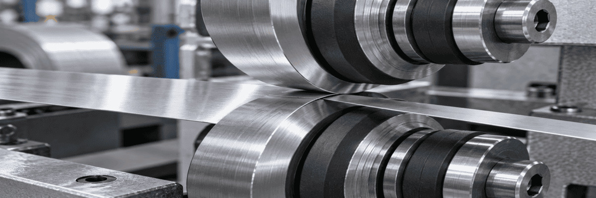
Vertical overlap—sometimes described as penetration—sets how far the upper and lower knives pass one another. Too little overlap can make fracture initiation unstable or leave an incomplete cut. Too much overlap increases side load and cutting force, magnifies sensitivity to runout and can shorten knife and bearing life.
Set overlap according to the slitter manufacturer’s procedure and the validated recipe for the material. After adjustment, rotate the tooling safely by hand or in the approved setup mode to confirm that no knife pair contacts and that the stack remains free. Never compensate for a dull knife by continually adding more overlap.
4. Keep Circular Knives Sharp, Flat and Concentric
A sharp cutting edge reduces the force needed to initiate a predictable fracture. As the edge radius grows, the strip experiences more deformation before separation, and burr height can increase. Local chipping may produce repeating defects, while side-face damage or poor surface finish can disturb clearance and promote metal pickup.
|
Knife Material |
Typical Direction |
Burr-Control Consideration |
|
D2 / SKD11 tool steel |
General steel and non-ferrous slitting |
Balanced wear resistance, availability and regrindability |
|
High-speed steel |
Higher-speed or tougher duty where hot hardness matters |
Useful when heat and edge stability limit conventional tool steel |
|
Tungsten carbide |
Thin, abrasive or long-run applications on stable equipment |
Excellent wear resistance but higher sensitivity to impact and misalignment |
5. Inspect the Entire Tooling Stack
Precision circular knives cannot hold clearance if the rest of the stack is inaccurate. Spacer thickness establishes knife position and finished strip width. Dirt, dents or metal particles trapped between tooling faces accumulate across the arbor and can shift the final knife position. Worn arbors, loose clamping, damaged bearings and incorrect rubber stripper rings can also produce lane-to-lane variation.
6. Stabilize the Coil and Slitting Line
A setup that produces a clean edge at low speed may deteriorate when the line accelerates. Changing tension, vibration, coil shape, lubrication or temperature alters how the strip enters and leaves the knife pair. Incoming thickness variation and mechanical properties can also change the fracture response even when the nominal coil grade is unchanged.
|
Process Area |
Variables to Verify |
|
Incoming coil |
Thickness profile, hardness/temper, camber, crown, surface coating |
|
Entry control |
Centering, strip tracking, hold-down and tension stability |
|
Slitter head |
Arbor rigidity, bearing condition, runout and vibration |
|
Tooling |
Knife edge, clearance, overlap, spacers and stripper rings |
|
Operating recipe |
Line speed, acceleration, lubrication and temperature |
|
Recoiling |
Separator arrangement, tension and strip-to-strip contact |
7. Build a Repeatable Burr-Control Routine
Random adjustment makes troubleshooting slower because several variables change at once. Establish a controlled inspection loop and preserve the successful settings as a material-specific recipe.
Conclusion
Reducing burrs in metal coil slitting requires control of the whole cutting system. Horizontal clearance and vertical overlap must match the coil’s thickness and mechanical properties; circular knives must remain sharp, flat and concentric; spacers and stripper rings must preserve the intended geometry; and the line must feed and rewind the strip without unstable tension or vibration.
Guangchuan Blade supplies precision rotary slitter knives and custom circular cutting solutions for stainless steel, carbon steel, aluminum, copper foil and other coil-processing applications. For a useful recommendation, send the blade drawing, coil grade and thickness range, machine model, current burr pattern and target edge specification with your inquiry.
Explore related blades: Circular Saw Blades / Circular Slitting Blades
Discuss a metal-slitting application: Contact Guangchuan Blade

Leave A Message
Scan to WhatsApp :

 English